An inductor of inductance L and resistor of resistance R are joined in series and connected by a source of frequency ω power dissipated in the circuit is a [{R2 + ω2L2}/V] b [{V2R}/{R2 + ω2L2}]c [V/{R2 + ω2L2}] d [√{R2 + ω2L2}/V2]
The correct option b [{V2R}/{R2 + ω2L2}]Explanation:Given is series R – L circuitHence impedance = Z = √[R2 + XL2]current I = [V / {|Z|}] = [V / √{R2 + XL2}]power dissipated in the circuit isP = I2R= [{V}/√{R2 + XL2}]2 ∙ R∴ P = [{V2R}/{R2 + XL2}]= [{V2R}/{R2 + ω2L2}].
Related Solutions
Two resistors of resistances R1 and R2 in series are connected to a source of emf E . Obtain expressions for potential difference across R1 and R2 .
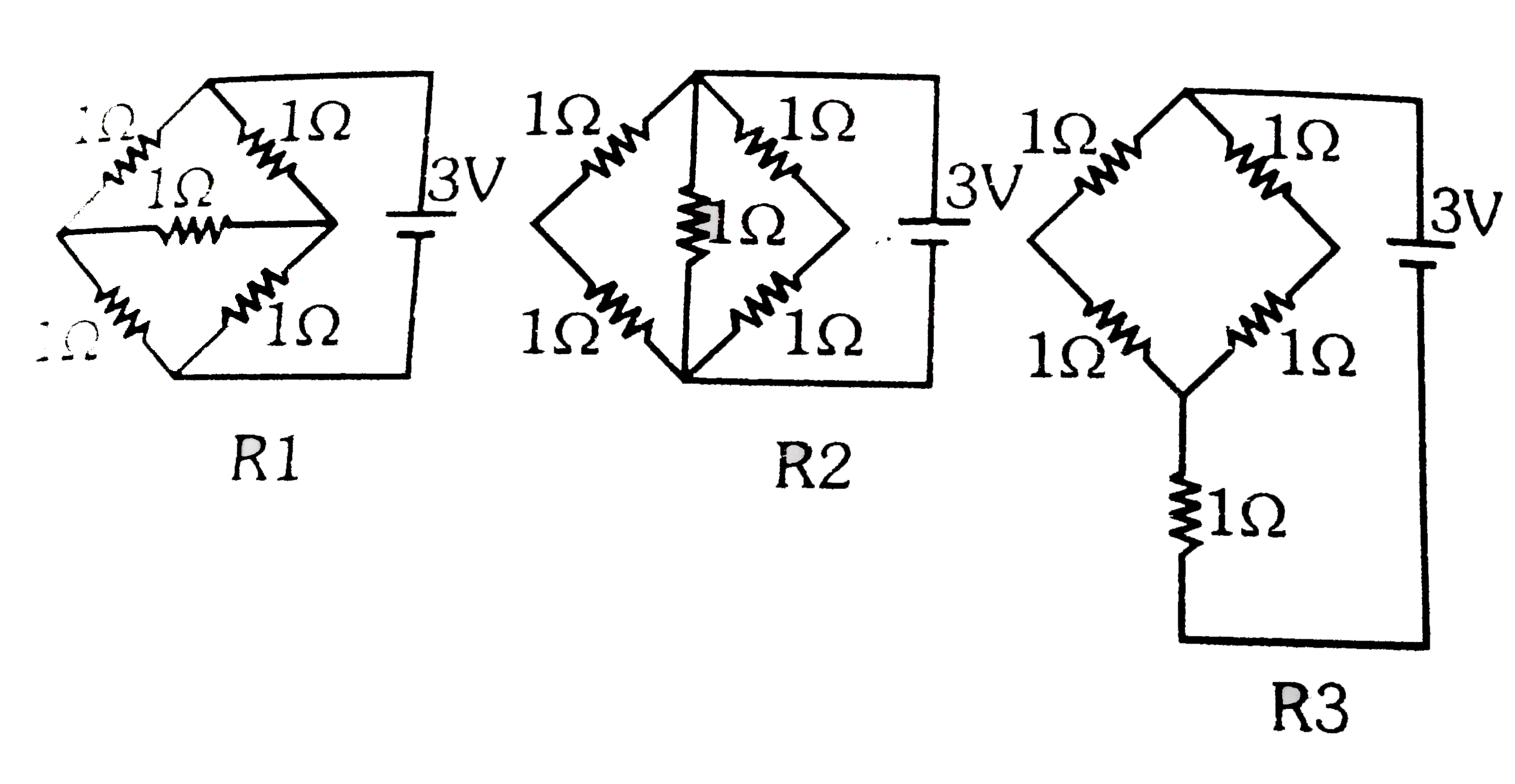
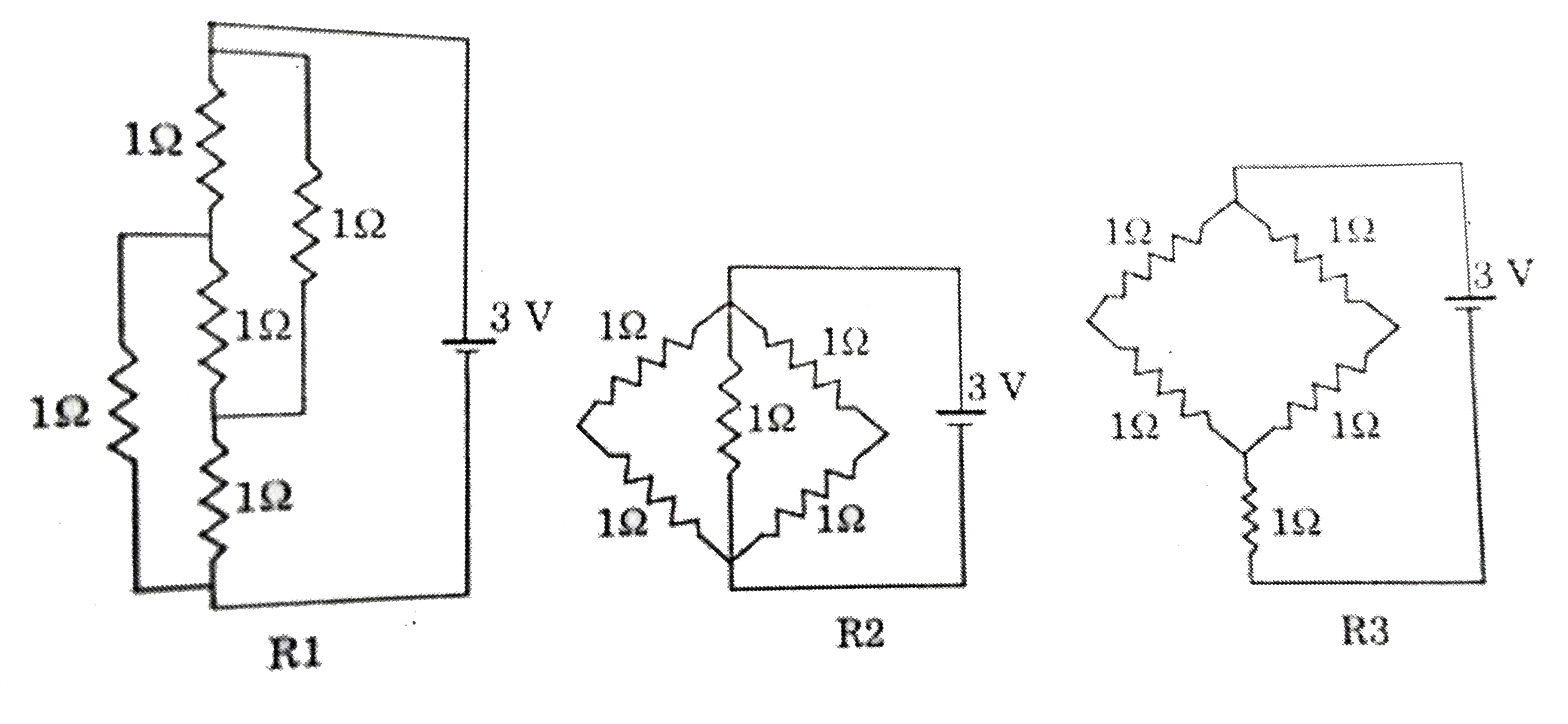
View SolutionFigure shows three resistor configurations R1,R2 and R3 connected to 3 V battery .

If the powers dissipated by the configuration R1,R2 and R3 are P1,P2 and P3, respectively, thenView SolutionFigure shows three resistor configurations R1,R2 and R3 connected to 3 V battery .

If the powers dissipated by the configuration R1,R2 and R3 are P1,P2 and P3, respectively, thenView SolutionFigure shows three resistor configurations R1,R2 and R3 connected to 3 V battery .

If the powers dissipated by the configuration R1,R2 and R3 are P1,P2 and P3, respectively, thenView SolutionFigure shows three resistor configurations R1,R2 and R3 connected to 3 V battery .

If the powers dissipated by the configuration R1,R2 and R3 are P1,P2 and P3, respectively, thenView SolutionFigure shows three resistor configurations R1,R2 and R3 connected to 3 V battery .

If the powers dissipated by the configuration R1,R2 and R3 are P1,P2 and P3, respectively, thenView SolutionAn inductor of inductance L and resistor R are joined together in series and connected by a source of frequency omega . The power dissipated in the circuit is
View SolutionAn inductor of inductance and ressistor of resistance are joined in series and connected by a source of frequency . Power dissipated in the circuit is
View SolutionAn inductor of inductance and ressistor of resistance are joined in series and connected by a source of frequency . Power dissipated in the circuit is
View SolutionAn inductance L and a resistor of resistance R are joined in series connected to a.c. source of frequency . What is the power dissipated to the circuit ?
View SolutionWhat is the phenotype of wheat kernal colour for the genotype: R1 R1 r2 r2?
View SolutionTwo resistance R1 and R2 connected in parallel, this equivalent resistance is.
View SolutionFigure shows three resistor configurations R1,R2 and R3 connected to 3V vattery If the prower dissipated by the configuration R1,R2 and R3 is P1 ,m P2 and P3 repecitively then
Figure
 View Solution
Reference to the problem 2 if R2 is short circuited and A and B are short circuited, find currents through each branch and the resistor R.
View SolutionTwo spherical conductors of radii R, and R2 (R2 > Ri) are charged. If they are connected by a conducting wire, find out the ratio of the surface charge densities on them.
View SolutionFormula OF R || r || r1 r2 and r3 with ProOF
View SolutionIllustration Based Upon r || r1|| r2 || r3
View SolutionProOF OF formula OF r, r1, r2 and r3
View SolutionIllustration based upon r,r1,r2,r3
View SolutionTwo resistance and (r1< r2) are joined in parallel. The equialent resistane R is such that
View Solution
