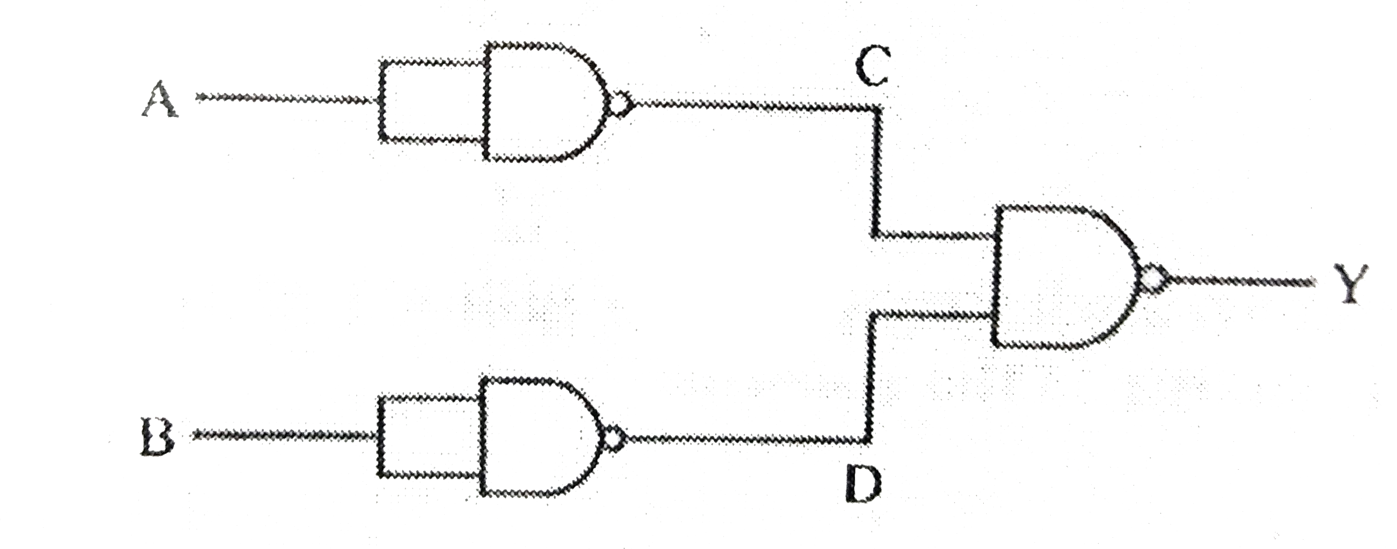
The circuit given below represents which of the logic operations?

AND
NOT
OR
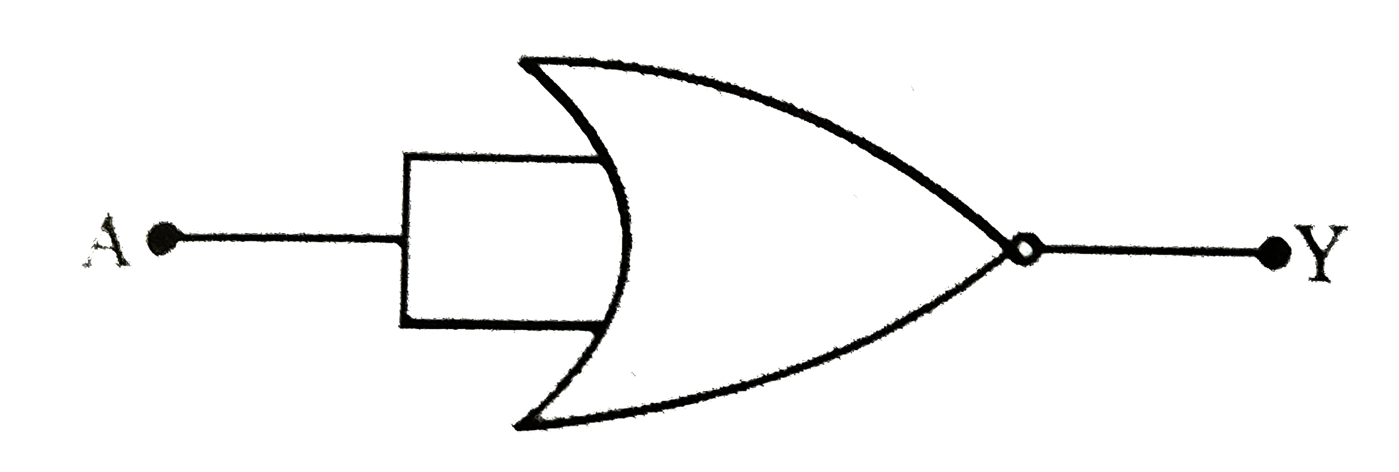
NOR
The correct Answer is:a
Let two inputs are A and B. The circuit can be shown as:

The two gates shown are NAND gates.
The output of gate ,1,Y1=¯¯¯¯¯¯¯¯A.B
The output gate 2,Y=¯¯¯¯¯¯¯¯¯Y1.Y1
or Y=¯¯¯¯¯¯¯¯¯¯¯¯¯¯¯¯¯¯¯¯¯¯¯¯¯A.B.¯¯¯¯¯¯¯¯A.B
=¯¯¯¯¯¯¯¯¯¯¯¯¯¯¯¯A.B
A.B
Thus, the combination behaves as it is an AND gate.
Topper's Solved these Questions
- BOOK - A2ZCHAPTER - MOCK TESTEXERCISE - Mock Test 245videos
MOCK TEST
- BOOK - A2ZCHAPTER - MOCK TESTEXERCISE - Mock Test 344videos
MOCK TEST
- BOOK - A2ZCHAPTER - MAGNETISM AND MATTEREXERCISE - Section D - Chapter End Test30videos
MAGNETISM AND MATTER
- BOOK - A2ZCHAPTER - NUCLEAR PHYSICSEXERCISE - Section D - Chapter End Test29videos
NUCLEAR PHYSICS
Similar Questions
Knowledge Check
- Question 1 - Select One
The logic circuit Fig. represents
 ANAND gate with outlet, O=¯¯¯X+¯¯¯YBNOR gate with outlet, O=¯¯¯¯¯¯¯¯¯¯¯X+YCNAND gate with outlat, O=¯¯¯¯¯¯¯¯X.YDNOR gate with outlet, O=¯¯¯X.¯¯¯Y
Identify the logic operation carried out.
 View Solution
Draw the output waveformed at X, using the given inputs A and B for the logic circuit shows below. Also, identify the logic operation performed by this circuit.
 View Solution
Draw the output waveform X, using the given inputs A and B for the logic circuit shows below. Also, identify the logic operation performed by this circuit.
 View Solution
Write the truth table for the logic circuit shown below and identify the logic operation performed by circuit.
 View Solution
The logic gate circuit given below acts as
 View Solution
Drawn the output waveform at X, using thye given inputs A and B for the logic circuit shown in Fig. Also identify the logic operation performed by this circuit.
 View Solution
You are given a circuit below write its truth table hence identify the logic operation carried out by the circuit draw the logic symbol of the gate it corresponds to
 View Solution


