A series combination of an inductor of self-inductance L, capacitor of capacitance C and resistor R is connected to an alternating voltage source of V=V0sinωt. The current through the circuit is I=I0sin(ωt−θ),where I0=V0√R2+(ω−1ωC)2andθ=tan−11R(ωL−1ωC).
Now that, the frequency of both voltage and current is f=ω2π . The rms value of these parameters during one complete cycles are Vrms=V0√2andIrms=I0√2 respectively. These values are shown in alternating voltmeter and ammeter.
The power consumed by the circuit P=VI. The mean value i.e., the effective power of the circuit in a complete cycle is ¯¯¯P=VrmsIrmscosθ. This cosθ is termed the power factor.
V=V0sinωt electromotive force is applied to an alternating circuit consisting of resistance R' and an inductor of self-inductance L. The phase difference between the voltage and current is Solution in Bengali
90∘
tan−1ωLR'
tan−1R'√R'2+ω2L2
√R'2+ω2L2R'
The correct Answer is:B
Step by step video, text & image solution for A series combination of an inductor of self-inductance L, capacitor of capacitance C and resistor R is connected to an alternating voltage source of V=V_0sinomegat. The current through the circuit is I=I_0sin(omegat-theta),where I_0=V_0/(sqrt(R^2+(omega-1/(omegaC))^2))andtheta=tan^-1 ""1/R(omegaL-1/(omegaC)). Now that, the frequency of both voltage and current is f=omega/(2pi) . The rms value of these parameters during one complete cycles are V_(rms)=V_0/sqrt2andI_(rms)=I_0/sqrt2 respectively. These values are shown in alternating voltmeter and ammeter. The power consumed by the circuit P=VI. The mean value i.e., the effective power of the circuit in a complete cycle is overlineP=V_(rms)I_(rms)costheta. This costheta is termed the power factor. V=V_0sinomegat electromotive force is applied to an alternating circuit consisting of resistance R' and an inductor of self-inductance L. The phase difference between the voltage and current is by Physics experts to help you in doubts & scoring excellent marks in Class 12 exams.
Topper's Solved these Questions
- BOOK - CHHAYA PUBLICATIONCHAPTER - ALTERNATING CURRENT EXERCISE - ENTRANCE CORNER (Integer Answer Type)8videos
ALTERNATING CURRENT
- BOOK - CHHAYA PUBLICATIONCHAPTER - ALTERNATING CURRENT EXERCISE - EXAMINATION ARCHIVE WITH SOLUTIONS (WBCHSE)20videos
ALTERNATING CURRENT
- BOOK - CHHAYA PUBLICATIONCHAPTER - ALTERNATING CURRENT EXERCISE - ENTRANCE CORNER (Matrix match type)5videos
ALTERNATING CURRENT
- BOOK - CHHAYA PUBLICATIONCHAPTER - EXERCISE - EXAMPLE1videos
- BOOK - CHHAYA PUBLICATIONCHAPTER - ATOMEXERCISE - CBSE SCANNER18videos
ATOM
Similar Questions
A resistance and a capacitor is connected in series with an alternating voltage of rms value 13 V. The terminal voltage of the resistor is 12V and that across the capacitor is (n+0.38)V. What is the value of n?
05:16View SolutionAn ac having a peak value 1.41 A is used to heat a wire. A dc producing the same heating rate will be approximately
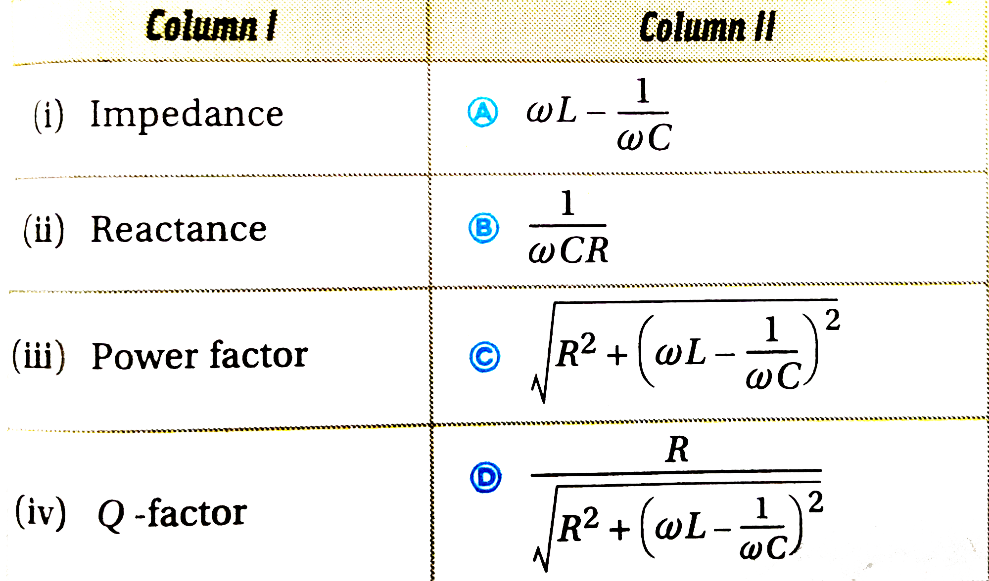
12:31View SolutionMatch the columns for a series LCR circuit.
 08:37View Solution
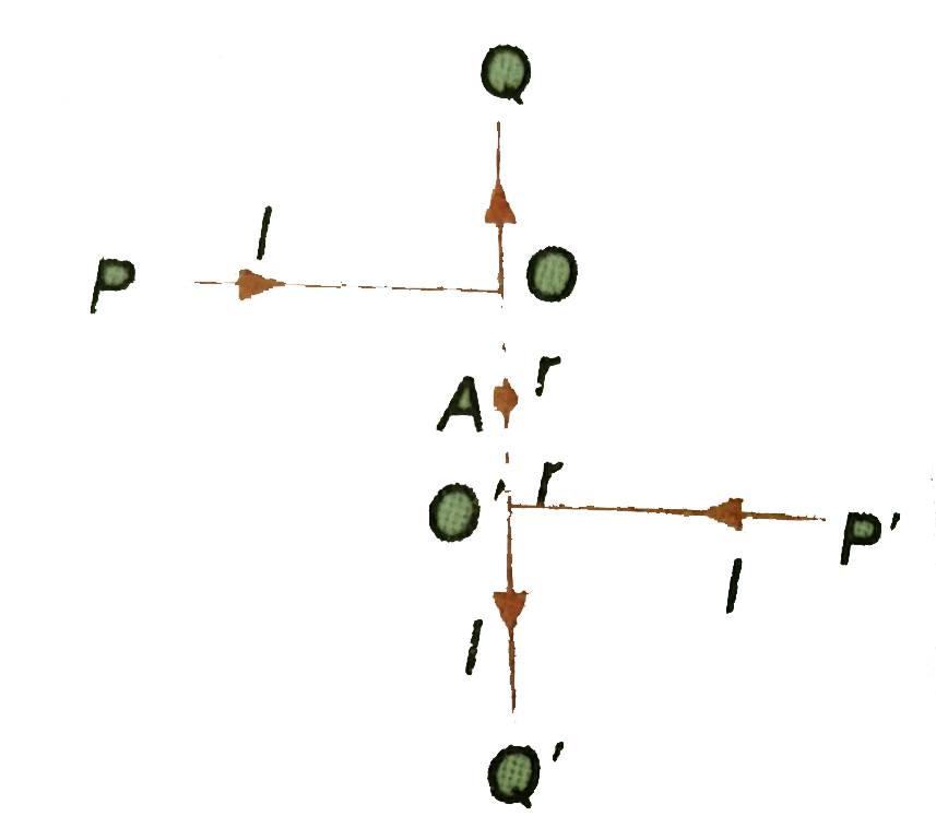
Through each of the two wires POQ and P'O'Q and electric current I is passing [Fig. 1.23]. The points Q,O,O and Q' are collinear. Determine the magnetic field at the midpoint A of OO'.
 06:21View Solution
Using de Broglie's hypothesis , explain with the help of a suitable diagram , Bohr's second postulate of quantisation of energy levels in a hydrogen atom.
05:29View SolutionAn AC voltage source V=V_0siomegat is connected across resistance R and capacitance C as shown in figureure. It is given that R=1/omegaC . The peak current is I_0 . If the angular frequency of the voltage source is changed to omega/sqrt3, then the new peak current in the circuit is .
05:29View Solutionप्रत्यावर्ती वोल्टेज स्त्रोत V=V0sinωt से प्रेरकत्व L , धारिता C तथा प्रतिरोध R तीनो श्रेणीक्रम में जुड़े है सिद्ध कीजिए कि परिपथ कि प्रतिबाधा Z=√R2+(ωL−1ωC)2 तथा tanϕ=ωL−1ωCR जहाँ ϕ धारा तथा वोल्टेज के बीच कालान्तर है ।
09:39View Solutionप्रत्यावर्ती वोल्टेज-स्रोत V=V0sinωt से प्रेरकत्व L, धारिता C तथा प्रतिरोध R तीनों श्रेणीक्रम में जुड़े हैं। सिद्ध कीजिए कि परिपथ की प्रतिबाधा Z का मान :
Z=√R2(ωL−1ωC)2 तथा tanϕ=ωL−1ωCR
जहाँ धारा तथा वोल्टेज के बीच कलान्तर है ।09:39View SolutionA series combination of an inductor of self-inductance L, capacitor of capacitance C and resistor R is connected to an alternating voltage source of V=V_0sinomegat . The current through the circuit is I=I_0sin(omegat-theta) ,where I_0=V_0/(sqrt(R^2+(omega-1/(omegaC))^2)) and theta=tan^-1 ""1/R(omegaL-1/(omegaC)) . Now that, the frequency of both voltage and current is f=omega/(2pi) . The rms value of these parameters during one complete cycles are V_(rms)=V_0/sqrt2 and I_(rms)=I_0/sqrt2 respectively. These values are shown in alternating voltmeter and ammeter. The power consumed by the circuit P=VI. The mean value i.e., the effective power of the circuit in a complete cycle is overlineP=V_(rms)I_(rms)costheta . This costheta is termed the power factor. the power factor of the circuit is question (i) is
04:58View SolutionA series combination of an inductor of self-inductance L, capacitor of capacitance C and resistor R is connected to an alternating voltage source of V=V0sinωt. The current through the circuit is I=I0sin(ωt−θ),where I0=V0√R2+(ω−1ωC)2andθ=tan−11R(ωL−1ωC).
Now that, the frequency of both voltage and current is f=ω2π . The rms value of these parameters during one complete cycles are Vrms=V0√2andIrms=I0√2 respectively. These values are shown in alternating voltmeter and ammeter.
The power consumed by the circuit P=VI. The mean value i.e., the effective power of the circuit in a complete cycle is ¯¯¯P=VrmsIrmscosθ. This cosθ is termed the power factor.
In the circuit in question (i) the inductor is replaced by a pure capacitor, the phase difference between the current and terminal voltage of the capacitor is04:07View SolutionA series combination of an inductor of self-inductance L, capacitor of capacitance C and resistor R is connected to an alternating voltage source of V=V0sinωt. The current through the circuit is I=I0sin(ωt−θ),where I0=V0√R2+(ω−1ωC)2andθ=tan−11R(ωL−1ωC).
Now that, the frequency of both voltage and current is f=ω2π . The rms value of these parameters during one complete cycles are Vrms=V0√2andIrms=I0√2 respectively. These values are shown in alternating voltmeter and ammeter.
The power consumed by the circuit P=VI. The mean value i.e., the effective power of the circuit in a complete cycle is ¯¯¯P=VrmsIrmscosθ. This cosθ is termed the power factor.
The power factor of the circuit in question (iii) is07:17View SolutionA series combination of an inductor of self-inductance L, capacitor of capacitance C and resistor R is connected to an alternating voltage source of V=V0sinωt. The current through the circuit is I=I0sin(ωt−θ),where I0=V0√R2+(ω−1ωC)2andθ=tan−11R(ωL−1ωC).
Now that, the frequency of both voltage and current is f=ω2π . The rms value of these parameters during one complete cycles are Vrms=V0√2andIrms=I0√2 respectively. These values are shown in alternating voltmeter and ammeter.
The power consumed by the circuit P=VI. The mean value i.e., the effective power of the circuit in a complete cycle is ¯¯¯P=VrmsIrmscosθ. This cosθ is termed the power factor.
The voltage applied in an LCR circuit having R=10Ω,L=10mHand C=1μFis V=20sinωt volt. For what frequency of the applied voltage will the current reach its peak value?02:18View SolutionA series combination of an inductor of self-inductance L, capacitor of capacitance C and resistor R is connected to an alternating voltage source of V=V0sinωt. The current through the circuit is I=I0sin(ωt−θ),where I0=V0√R2+(ω−1ωC)2andθ=tan−11R(ωL−1ωC).
Now that, the frequency of both voltage and current is f=ω2π . The rms value of these parameters during one complete cycles are Vrms=V0√2andIrms=I0√2 respectively. These values are shown in alternating voltmeter and ammeter.
The power consumed by the circuit P=VI. The mean value i.e., the effective power of the circuit in a complete cycle is ¯¯¯P=VrmsIrmscosθ. This cosθ is termed the power factor.
The phase difference between the voltage and peak current in question (v) isView SolutionA series combination of an inductor of self-inductance L, capacitor of capacitance C and resistor R is connected to an alternating voltage source of V=V0sinωt. The current through the circuit is I=I0sin(ωt−θ),where I0=V0√R2+(ω−1ωC)2andθ=tan−11R(ωL−1ωC).
Now that, the frequency of both voltage and current is f=ω2π . The rms value of these parameters during one complete cycles are Vrms=V0√2andIrms=I0√2 respectively. These values are shown in alternating voltmeter and ammeter.
The power consumed by the circuit P=VI. The mean value i.e., the effective power of the circuit in a complete cycle is ¯¯¯P=VrmsIrmscosθ. This cosθ is termed the power factor.
Which element is responsible for the power consumption in an alternating current circuit?02:55View SolutionA series combination of an inductor of self-inductance L, capacitor of capacitance C and resistor R is connected to an alternating voltage source of V=V_0sinomegat . The current through the circuit is I=I_0sin(omegat-theta) ,where I_0=V_0/(sqrt(R^2+(omega-1/(omegaC))^2)) and theta=tan^-1 ""1/R(omegaL-1/(omegaC)) . Now that, the frequency of both voltage and current is f=omega/(2pi) . The rms value of these parameters during one complete cycles are V_(rms)=V_0/sqrt2 and I_(rms)=I_0/sqrt2 respectively. These values are shown in alternating voltmeter and ammeter. The power consumed by the circuit P=VI. The mean value i.e., the effective power of the circuit in a complete cycle is overlineP=V_(rms)I_(rms)costheta . This costheta is termed the power factor. The frequency of the applied alternating voltage in an ac circuit is 50 Hz.Resistance and self inductance are 37.6Omega and 120 mH . The phase difference between the voltage and current is
03:07View Solution

