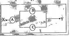
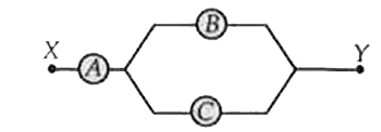
A,B and C are voltmetres of resistance R, 1.5R and 3R as shown in the figure. When some potential difference is applied between X and Y the voltmetre readings are VA,VB and VC respectively , Then:
 Solution in Tamil
VA≠VB=VC
VA=VB≠VC
VA≠VB≠VC
VA=VB=VC
Step by step video & image solution for A,B and C are voltmetres of resistance R, 1.5R and 3R as shown in the figure. When some potential difference is applied between X and Y the voltmetre readings are V_A,V_B and V_C respectively , Then: by Physics experts to help you in doubts & scoring excellent marks in Class 12 exams.
Topper's Solved these Questions
Similar Questions
Nickel shows ferromagnetic property at room temperature. If the temperature is increased beryond Curie temperatue,then it will show
03:50View SolutionThe work function of a surface of a photosensitive material 6.2eV . The wavelength of the incident radiation for which the stopping potentials is 5V lies in the:
05:10View SolutionA,B and C are voltmeters of resistances R,1.5R and 3R respectively. When some potential difference is applied between x and y the voltmeter readings are VA,V_BandV_C, then
 02:27View Solution
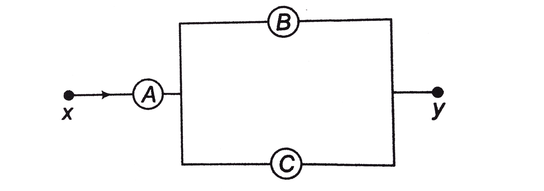
Find out the following
a. VA−VB
b. VB−VC
c. VC−VA
d. VD−VC
e. VA−VD
f. Arrange the order of potential for points (A, B,C and D).
 .02:58View Solution
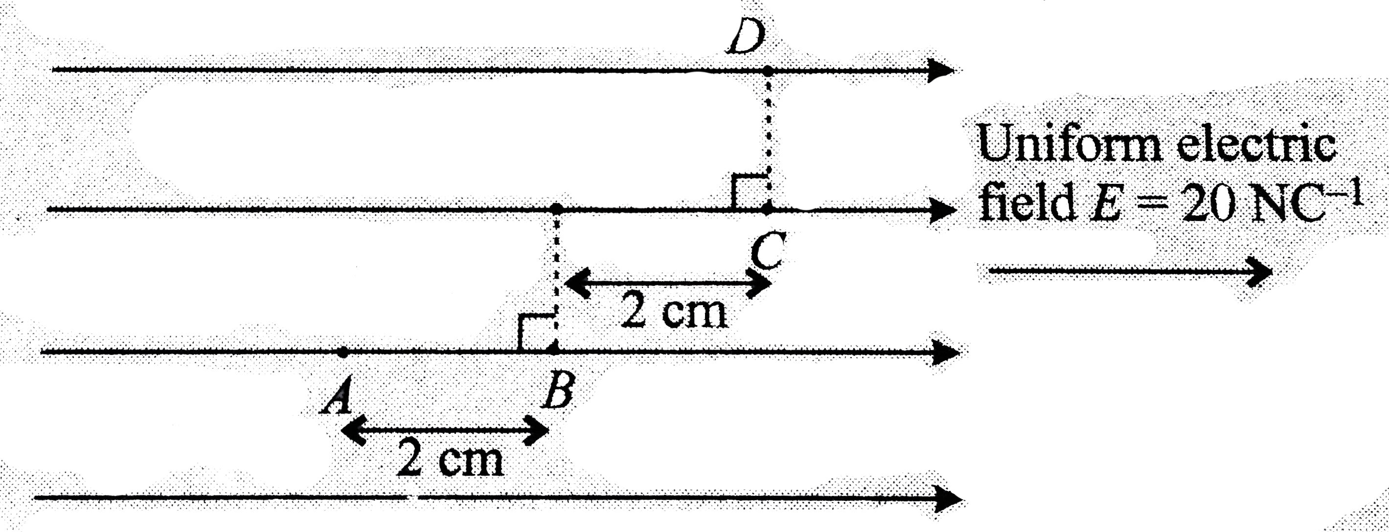
The potential difference (VA−VB) between the point A and B as shown in the figure is
 01:52View Solution
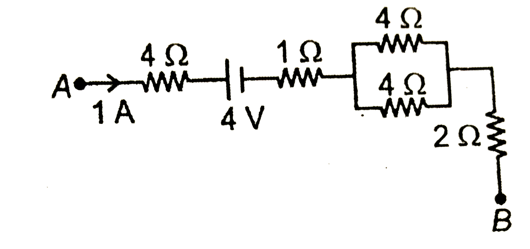
A,B and C are voltmeters of resistance R, 1.5 R and 3R respectively as shown in the figure. When some potential difference is applied between X and Y, the voltmeter reading are V_A , V_B and V_C respectively.
03:20View SolutionA battery of e.m.f. 10 V is connected to resistances as shown in figure The potential difference V_A-V_B between the points A and B is
06:15View SolutionThe voltmeters A,B, and C having resistance R, 1.5R and 3R respectively are used in a circuit as shown, When a P.D. is applied between X and Y, the reading of the voltmeters are V1,V2 and V3 respectively Then
 03:33View Solution
A, B and C arc voltmeters of resistance R, 1.5R and 3R respectively as shown in the figure. When some potential difference is applied between X and Y, the voltmeter readings are VA,VBandVC repsectively. Then :
03:58View SolutionA,B and C are voltmeters of resistance R, 1.5 R and 3R respectively as shown in the fig. When some potential difference is applied between X and Y, the voltmeter reading are VA,VBandVC respectively.
 View Solution
A, B and C are voltmeters of resistance R, 1.5R and 3R respectively as shown in the figure. When some potential difference is aaplied between X and Y, the voltmeter readings are VA,VB and VC respectively, then
 02:18View Solution
A, B and C are voltmeters of resistance R, 1.5R and 3R respectively as in fig. when some P.D. is applied between x and y, the voltmeter readings are V_A, V_B and V_C respectively, then:
02:27View SolutionA,B and C are voltmeters of resistances R,1.5R and 3R respectively. When some potential difference is applied between x and y the voltmeter readings are VA,V_BandV_C, then
 01:58View Solution
A, B and C are voltmeters of resistances R, 1.5R and 3R respectively. When some potential difference is applied between x and y the voltmeter readings are V_A, V _B and V_C, then
08:30View SolutionA, B and C are voltmeters of resistances R, 1.5R and 3R respectively. When some potential difference is applied between x and y the voltmeter readings are V_A, V _B and V_C, then
02:23View SolutionA, B, C are three voltmeter of resistances 4000 Omega, 6000 Omega and 12000 Omega . When a potential difference is applied between X and Y, Voltmeter reading are V_A, V_B and V_C . Then
04:00View Solution

