Draw a simple diagram ofa fire tongs and mark on it the fulcrum F and the points of application of load L and effort E. (a) Name the class of lever. (b) if load arm is 15 cm and effort arm is 5 cm. what is its mechanical adavantage?
Step-by-Step Solution:
1. Draw the Diagram of Fire Tongs:
- Start by sketching the fire tongs. The tongs consist of two arms that pivot at a fulcrum.
- Mark the fulcrum (F) at the point where the two arms meet.
- Identify the point where the load (L) is applied, which is typically at the end of one arm where the object is held.
- Mark the point where the effort (E) is applied, which is at the end of the other arm where the user applies force to operate the tongs.
Diagram:
E|∣|∣∣∣F−−−−−L
2. Identify the Class of Lever:
- In the case of fire tongs, the effort is applied between the load and the fulcrum. This configuration places the load at one end, the effort in the middle, and the fulcrum at the other end.
- This arrangement classifies the fire tongs as a third class lever.
3. Calculate the Mechanical Advantage:
- The mechanical advantage (MA) of a lever is calculated using the formula:
\(
\text{Mechanical Advantage (MA)} = \frac{\text{Effort Arm}}{\text{Load Arm}}
\)
- Given:
- Load Arm = 15 cm
- Effort Arm = 5 cm
- Substitute the values into the formula:
\(
\text{MA} = \frac{5 \, \text{cm}}{15 \, \text{cm}} = \frac{1}{3} \approx 0.33
\)
Final Answers:
(a) The class of lever is third class lever.
(b) The mechanical advantage is 0.33.
- Start by sketching the fire tongs. The tongs consist of two arms that pivot at a fulcrum.
- Mark the fulcrum (F) at the point where the two arms meet.
- Identify the point where the load (L) is applied, which is typically at the end of one arm where the object is held.
- Mark the point where the effort (E) is applied, which is at the end of the other arm where the user applies force to operate the tongs.
E|∣|∣∣∣F−−−−−L
- In the case of fire tongs, the effort is applied between the load and the fulcrum. This configuration places the load at one end, the effort in the middle, and the fulcrum at the other end.
- This arrangement classifies the fire tongs as a third class lever.
- The mechanical advantage (MA) of a lever is calculated using the formula:
\(
\text{Mechanical Advantage (MA)} = \frac{\text{Effort Arm}}{\text{Load Arm}}
\)
- Given:
- Load Arm = 15 cm
- Effort Arm = 5 cm
- Substitute the values into the formula:
\(
\text{MA} = \frac{5 \, \text{cm}}{15 \, \text{cm}} = \frac{1}{3} \approx 0.33
\)
(a) The class of lever is third class lever.
(b) The mechanical advantage is 0.33.
Topper's Solved these Questions
- BOOK - ICSECHAPTER - MACHINESEXERCISE - EXERCISE-3(A)40videos
MACHINES
- BOOK - ICSECHAPTER - MACHINESEXERCISE - EXERCISE-3(A) MULTIPLE CHOICE TYPE5videos
MACHINES
- BOOK - ICSECHAPTER - HOUSEHOLD CIRCUITS EXERCISE - EXERCISE -9(B) (MULTIPLE CHOICE TYPE)2videos
HOUSEHOLD CIRCUITS
- BOOK - ICSECHAPTER - QUESTION PAPER 2022 TERM 1EXERCISE - MULTIPLE CHOICE QUESTIONS40videos
QUESTION PAPER 2022 TERM 1
Similar Questions
Figure, shows a lemon crushes,
(a) In the diagram, mark the position of the fulcrum F and the line of action of load L and effort E.

(b) Name the class of lever.View SolutionA lever of length 9 cm has its load arm 5 cm long and the effort arm is 9 cm long. (a) to which class does it belong ?
(b) Draw a diagram of the lever showing the position of the fulcrum F and directions of both the load L and effort E. (c) what is the mechanical advantage and velocity ratio if the efficiency is 100%?
(d) What will be the mechanical advantage and velocity ratio if the efficiency becomes 50%?View SolutionIndicate the positions of load L, effort E and fulcrum F in the forearm shown alongsind in figure. Name the class of leverl.
 .View Solution
A man uses a crowbar of length 1.5m to raise a load of 75 kgf by putting a sharp edge below the bar at a distance of 1 m from his hand. (a) draw a diagram of the arrangement showing the fulcrum (F), load (L) and effort (E) with their direction. (b) state the kind of lever. (c) Calculate : (i) load arm, (ii) effort arm, (iii) mechanical advantage, and (iv) the effort needed.
View SolutionThe diagram below shows a rod lifting a stone.
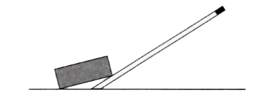
(a) Mark position of fulcrum F and draw arrows to show the directions of load L and effort E. (b) What class of lever is the rod ? (c) Give one more example of the same class of lever stated in part (b).
 .View Solution
A pulley system has a velocity ratio 3. draw a diagram showing the point of applicationi and direction of load (L), effort (E) and tension (T). It lifts a load of 150 N by an effot of 60 N. calculate its mechanical advantage. Is the pulley system ideal ? Give reason.
View SolutionCalculate the ideal mechanical advantage of a lever in which the effort arm is 60 cm and the load arm is 4 cm.
View SolutionA block and tackle system has velocity ratio 3. draw a labelled diagram of the system indicating the points of application and the direction of load L and effort E. A man can exert a pull of 200 kgf. (a) What is the maximum load he can raise with this pulley system if its efficiency is 60% ? (b) if the effort end moves a distance 60 cm, what distance does the load move ?
View SolutionDraw a diagram to show a block and tackle pulley system having a velocity ratio of 3 marking the direction of load (L), effort (E) and tension (T).
 View Solution
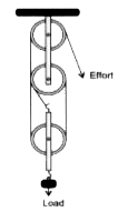
Draw a diagram of a block and tackle system of pulleys having a velocity ratio of 5. in your diagram indicate clearly the points of application and the directions of the load L and effort E. also mark the tension T in each strand.
View Solution

