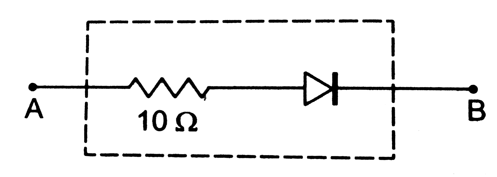
Draw the current-voltage characteristics for the device shown in figure between the terminal A and B.
Solution in Tamil
Drow yourself.
Topper's Solved these Questions
Similar Questions
In a semiconductor,
View SolutionFind the luminous flux of 10 W source of 600 nm. The relative luminosity at 600 nm is 0.6.
View SolutionIn an experiment to measure the speed of light by Fizeau's apparatus, following data are used :
Distance between the mirrors = 12.0 km,
Number of teeth in the wheel = 180.
Find the minimum angular speed of the wheel for which the image is not seen.
View SolutionThe current-voltage graph of a device is shown in figure. The resistance is negative in region.
View SolutionConsider a box with three terminals on top of it as shown in figure.
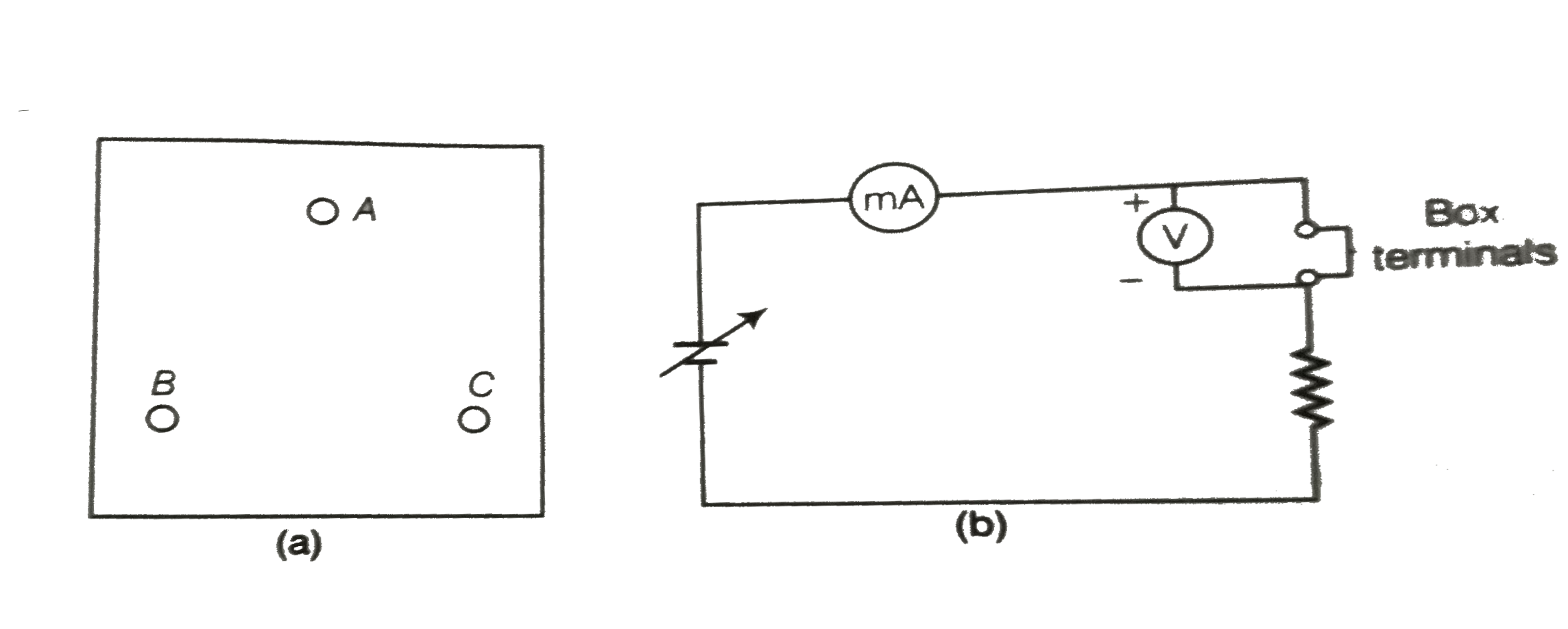
Three components namely, two germanium diodes and one resistor are connected across these three terminals in some arrangement
A student performs an experiment in which any two of these three terminals are connected in the circuit shown in figure.
The student obtains graphs of current-voltage characteristics for unknown combination of components between the two terminals connected in the circuit. The graphs are
(i) When A is positive and B is negative
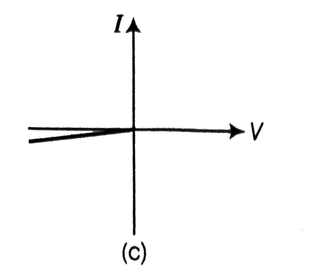
(ii) When A is negative and B is positive
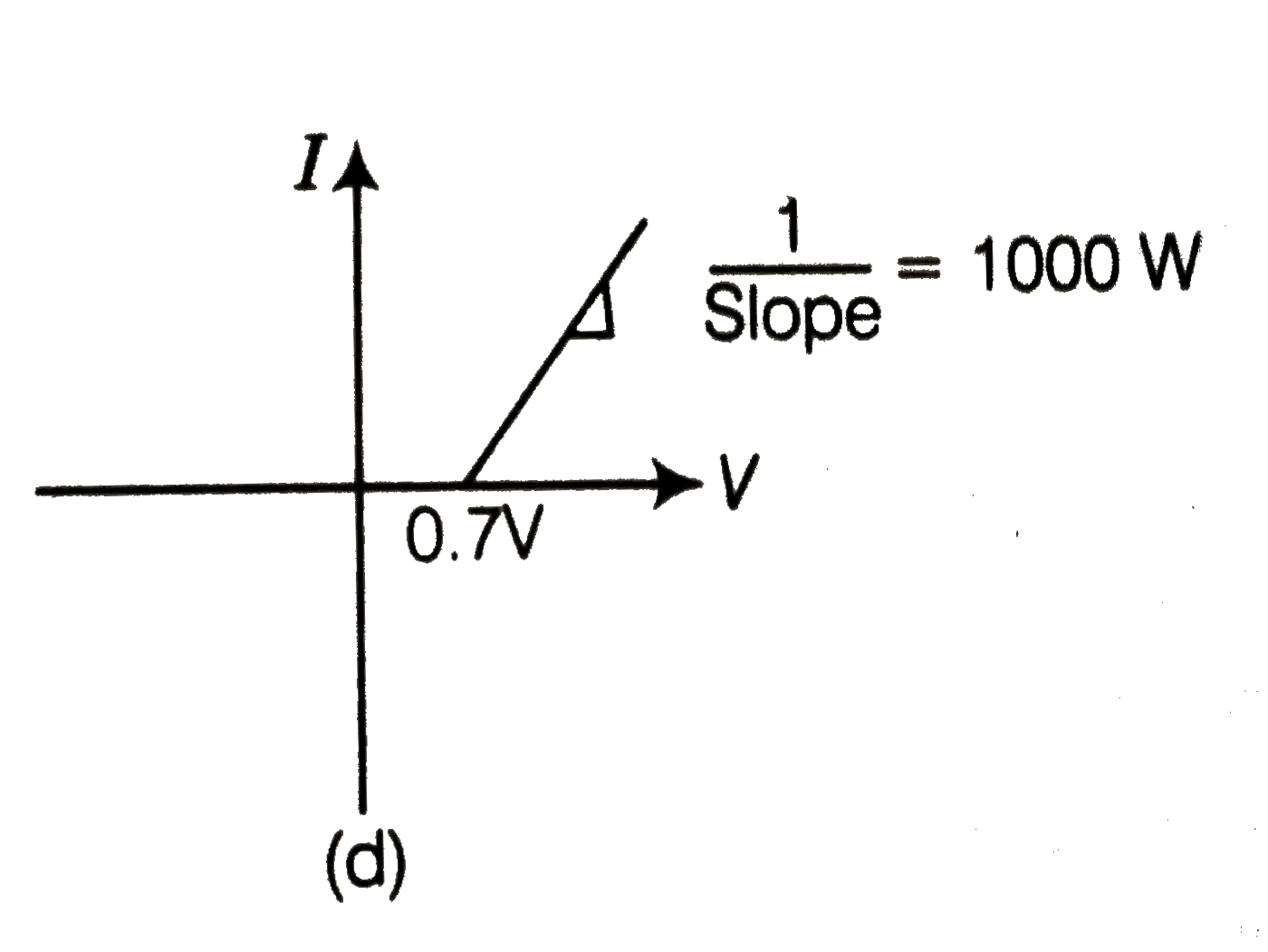
(iii) When B is negative and C is positve
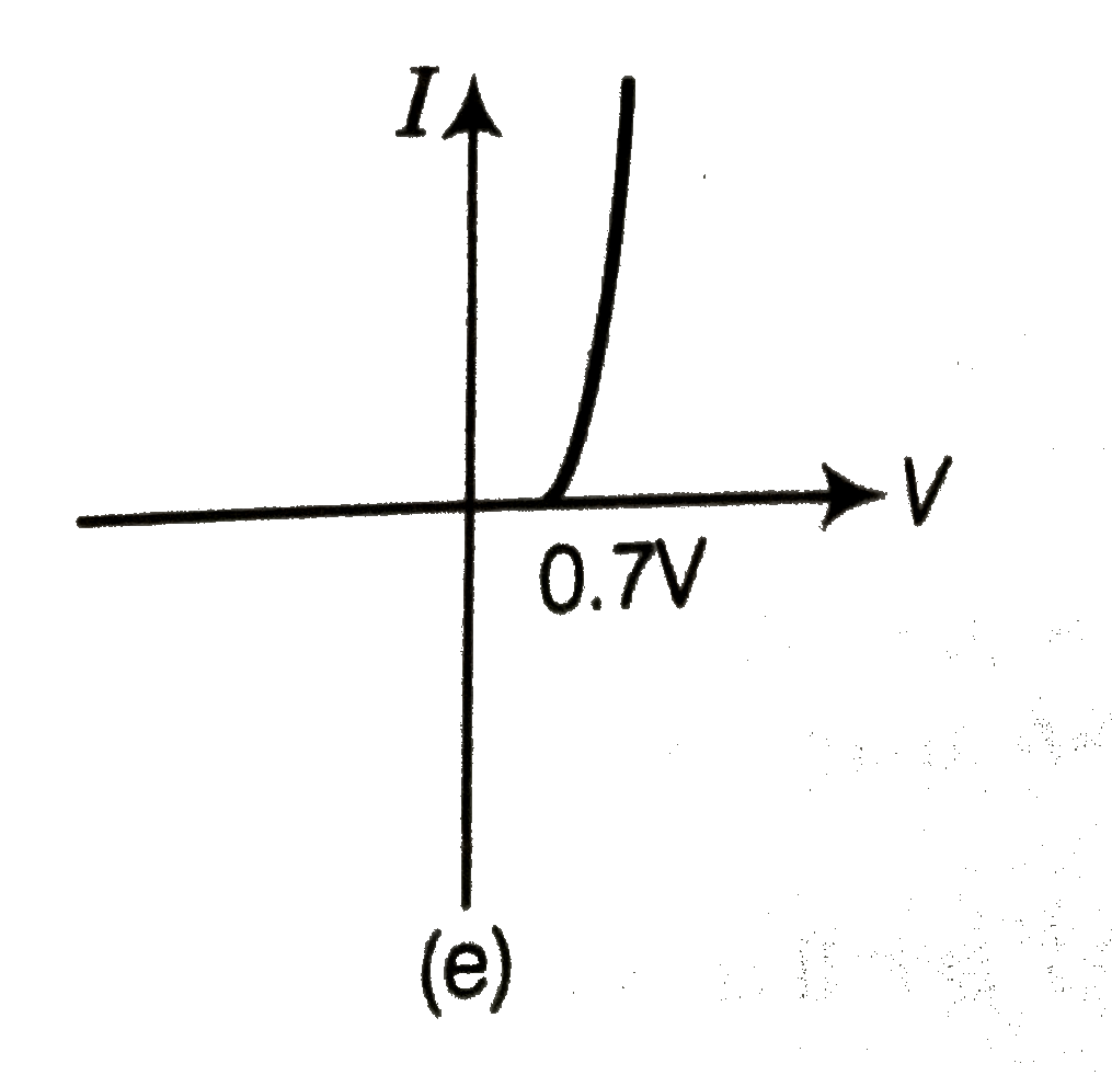
(iv) When B is positive and C is neagtive
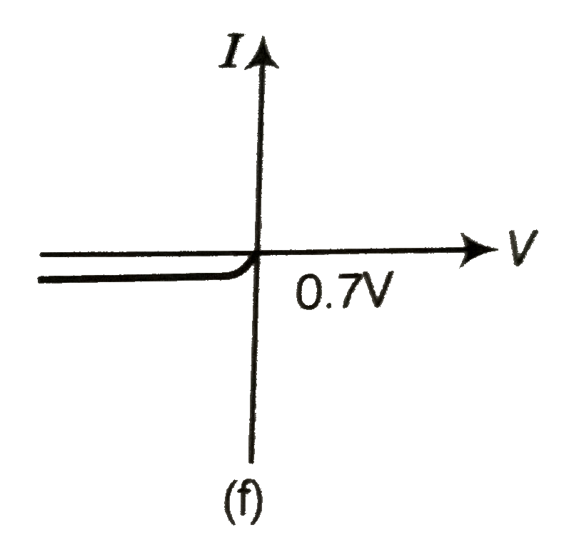
(v) When A is positive and C is negative
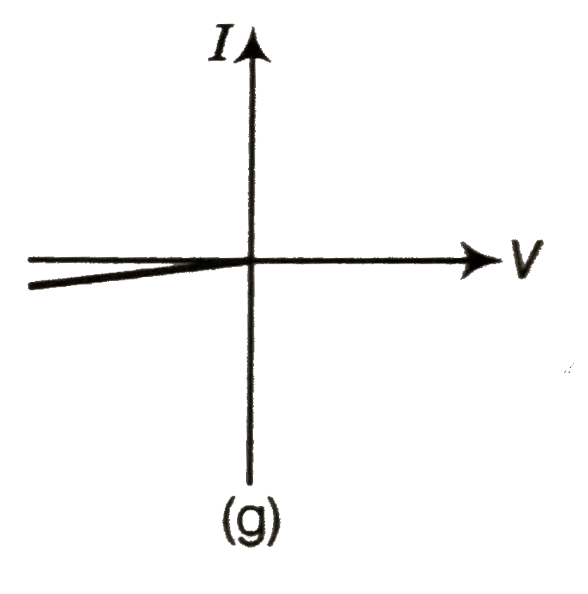
(vi) When A is negative and C is positive
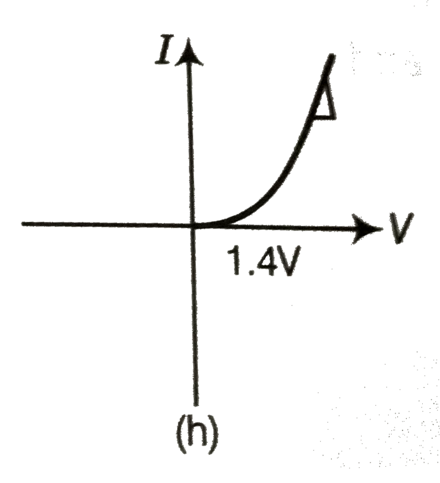
From these graphs of current − voltage characteristic shown in fig. (c) to (h) determine the arrangement of components between A, B and C.
View SolutionFind the equivalent resistance between the terminal points A and B in the network shown in the figure.
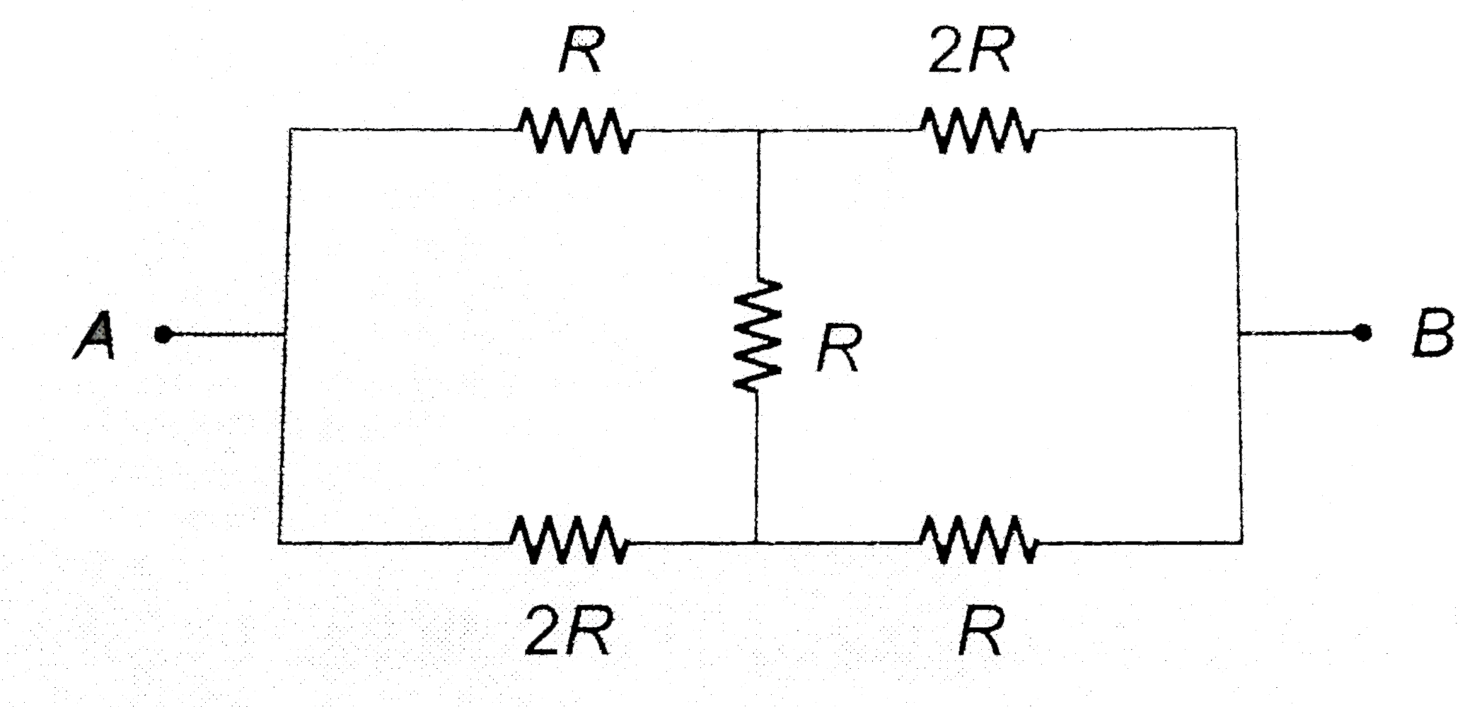 .
.
View SolutionCurrent-voltage characteristics of two elements A and B are as shown below in Figs. (a) and (b). (a) Which of the following graphs represents current voltage characteristics for their series combinations ?
View SolutionDraw the voltage current characteristic fo a zener diode.
View SolutionFind the equivalent capacitance between terminals A and B in the circuit shown in figure:
View SolutionCalculate (i) current in the 6Omega resistor, (ii) terminal voltage across the 4V cell in the circuit shown in figure.
View Solutionकिसी सेल से ली गई धारा I और उसके टर्मिनल वोल्टेज V के बीच ग्राफ खींचिए ।
View SolutionThe equivalent resistance between the terminals A and B in the network shown in the figure is
View SolutionDraw the voltage-current charateristics of a p-n junction and compare it with the characteristics of a resistor.
View SolutionCurrent-voltage characteristics of two elements A and B are as shown. (fig. (a) and (b) ] Which of the following graphs represents current- voltage characteristics for their series combination
View SolutionDraw the voltage-current characteristic of a Zener diode.
View SolutionIf voltage V is applied across terminals a and b of the circuit shown in the following figure, which of the statements below is true? (Notation: i_4 is current through 4.00Omega resistor,...)
View Solution
