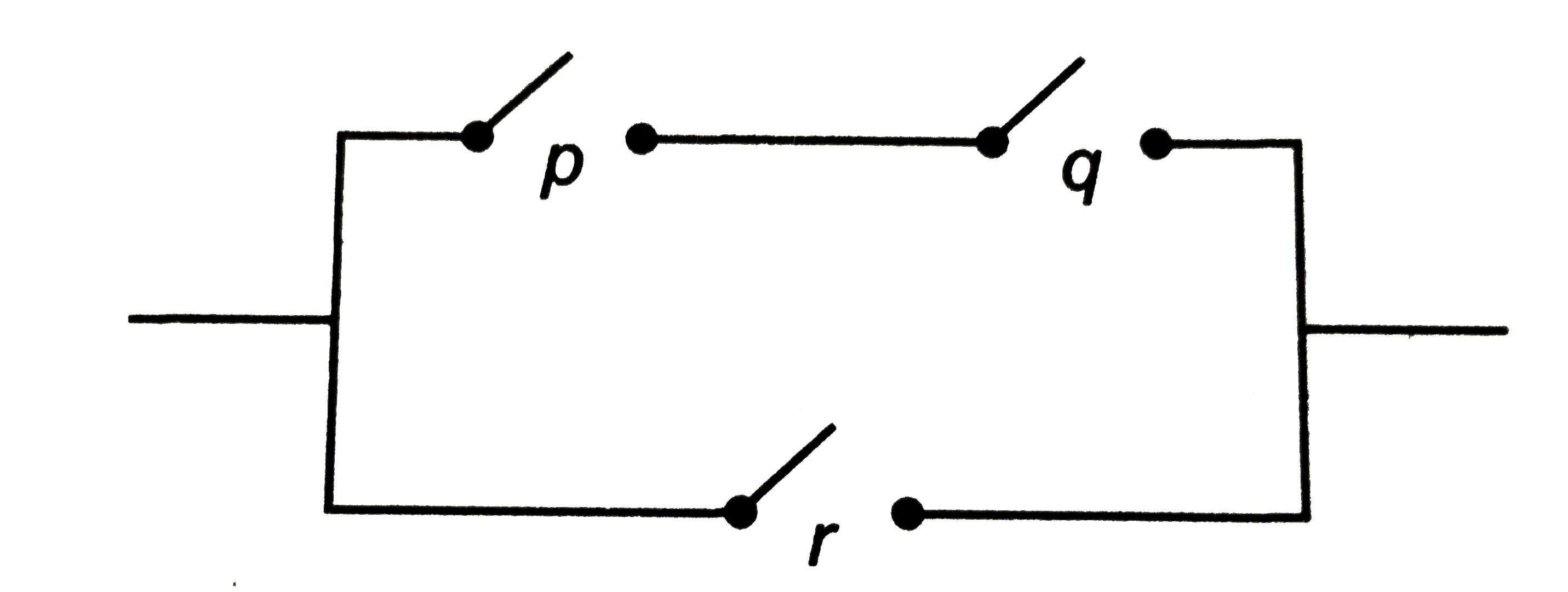
Imagine a would where free magnetic charges exist. In this world, a circuit is made with a U shape wire and a rod free to slide on it. A current carried by free magnetic charges can flow in the circuit. When the circuit is placed in a uniform electric field. E perpendicular to the plane of the plane of the circuit and the rod is pulled to the right with a constant speed v, the "magnetic EMF" in the current and the direction of the corresponding current. arising because of changing electric flux will be (l is the length of the rod and c is speed of light).
vEl clockwise.
vEL counterclock wise
vElc2 clockwise
vElc2 counterclockwise
To solve the problem step by step, we need to analyze the situation involving the U-shaped wire, the rod, the electric field, and the concept of induced EMF due to changing electric flux.
Step 1: Understanding the Setup
We have a U-shaped wire with a rod that can slide on it. The circuit is placed in a uniform electric field E that is perpendicular to the plane of the circuit. The rod is pulled to the right with a constant speed v.
Hint: Visualize the circuit and the electric field. The electric field is acting perpendicular to the area formed by the U-shaped wire.
Step 2: Calculate the Electric Flux
The electric flux ΦE through the area of the circuit can be expressed as:
ΦE=E⋅A
where A is the area of the circuit. The area A can be expressed in terms of the length of the rod L and the displacement x of the rod:
A=L⋅x
Thus, the electric flux becomes:
ΦE=E⋅(L⋅x)
Hint: Remember that the area changes as the rod moves, which affects the electric flux.
Step 3: Determine the Rate of Change of Electric Flux
To find the induced EMF, we need the rate of change of electric flux with respect to time:
dΦEdt=E⋅L⋅dxdt
Since the rod is moving with a constant speed v, we have dxdt=v. Therefore:
dΦEdt=E⋅L⋅v
Hint: The induced EMF is related to how quickly the electric flux changes.
Step 4: Calculate the Induced EMF
According to Faraday's law of electromagnetic induction, the induced EMF E is given by:
E=−dΦEdt
Substituting the expression for the rate of change of electric flux:
E=−E⋅L⋅v
Hint: The negative sign indicates the direction of the induced EMF according to Lenz's law.
Step 5: Determine the Direction of the Induced Current
Using Lenz's law, the direction of the induced current will be such that it opposes the change in flux. As the area is increasing due to the rod moving to the right, the induced current will flow in a direction that creates a magnetic field opposing the increase in electric flux.
1. If the electric field E is directed downward, the induced current will be in a counterclockwise direction.
2. If the electric field E is directed upward, the induced current will be in a clockwise direction.
Hint: Think about how the induced current must act to oppose the change in flux.
Final Answer
The induced EMF in the circuit is given by:
E=−E⋅L⋅vc2
The direction of the induced current will depend on the direction of the electric field E:
- Clockwise if E is upward.
- Counterclockwise if E is downward.
We have a U-shaped wire with a rod that can slide on it. The circuit is placed in a uniform electric field E that is perpendicular to the plane of the circuit. The rod is pulled to the right with a constant speed v.
The electric flux ΦE through the area of the circuit can be expressed as:
ΦE=E⋅A
where A is the area of the circuit. The area A can be expressed in terms of the length of the rod L and the displacement x of the rod:
A=L⋅x
Thus, the electric flux becomes:
ΦE=E⋅(L⋅x)
To find the induced EMF, we need the rate of change of electric flux with respect to time:
dΦEdt=E⋅L⋅dxdt
Since the rod is moving with a constant speed v, we have dxdt=v. Therefore:
dΦEdt=E⋅L⋅v
According to Faraday's law of electromagnetic induction, the induced EMF E is given by:
E=−dΦEdt
Substituting the expression for the rate of change of electric flux:
E=−E⋅L⋅v
Using Lenz's law, the direction of the induced current will be such that it opposes the change in flux. As the area is increasing due to the rod moving to the right, the induced current will flow in a direction that creates a magnetic field opposing the increase in electric flux.
2. If the electric field E is directed upward, the induced current will be in a clockwise direction.
The induced EMF in the circuit is given by:
E=−E⋅L⋅vc2
The direction of the induced current will depend on the direction of the electric field E:
- Clockwise if E is upward.
- Counterclockwise if E is downward.
Topper's Solved these Questions
- BOOK - KVPY PREVIOUS YEARCHAPTER - KVPY 2021EXERCISE - PART I (Chemistry)2videos
KVPY 2021
- BOOK - KVPY PREVIOUS YEARCHAPTER - KVPY 2021EXERCISE - PART-I Physics13videos
KVPY 2021
- BOOK - KVPY PREVIOUS YEARCHAPTER - KVPYEXERCISE - All Questions415videos
KVPY
- BOOK - KVPY PREVIOUS YEARCHAPTER - MOCK TEST 1EXERCISE - EXERCISE23videos
MOCK TEST 1
Similar Questions
Knowledge Check
- Question 1 - Select One
Imagine a would where free magnetic charges exist. In this world, a circuit is made with a U shape wire and a rod free to slide on it. A current carried by free magnetic charges can flow in the circuit. When the circuit is placed in a uniform electric field. E perpendicular to the plane of the plane of the circuit and the rod is pulled to the right with a constant speed v, the "magnetic EMF" in the current and the direction of the corresponding current. arising because of changing electric flux will be (l is the length of the rod and c is speed of light).
AvEl clockwiseBvEL counterclockwiseCvElc2 clockwiseDvElc2 counterclockwise - Question 2 - Select One
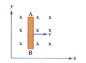
A conducting rod AB moves parallel to x-axis in a uniform magnetic field pointing perpendicular and into the plane of paper. The end A of the rod
 Agets positively chargedBgets negatively chargedCremains neutralDgets positively charged first and then negatively charged
 - Question 3 - Select One
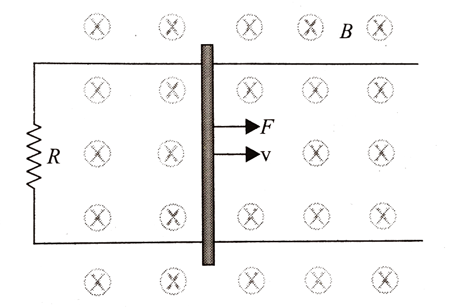
A rod closing the circuit shown in Fig moves along a U shaped wire at a constant speed v under the action of the force F. The circuit is in a uniform magnetic field perpendicular to the plane. Calculate F if the rate of heat generation in the circuit is Q.
 AF=QvBF=QvCF=vQDF=√Qv
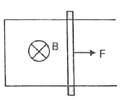
A rod closing the circuit shoew in the figure moves along a LI- shaped wire at a constant speed v under the action of the force F . The circult is in a unifron magnetic field perpendicluar to the plane . Calculate F if rate of heat generation in the circuit is Q.
 View Solution
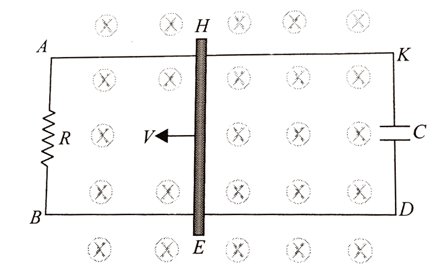
In the circuit shown in Fig. A conducting wire HE is moved with a constant speed v towards left. The complete circuit is placed in a uniform magnetic field →B perpendicular to the plane of circuit inwards. The current in HKDE is
 View Solution
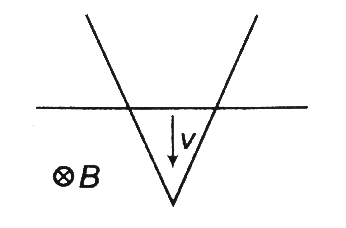
A wire is bent in the form of a V shape and placed in a horizontal plane. There exists a uniform magnetic field B perpendicular to the plane of the wire. A uniform conducting rod starts sliding over the V shaped wire with a constant speed v as shown in the figure. If the wire no resistance, the current in rod wil
 View Solution
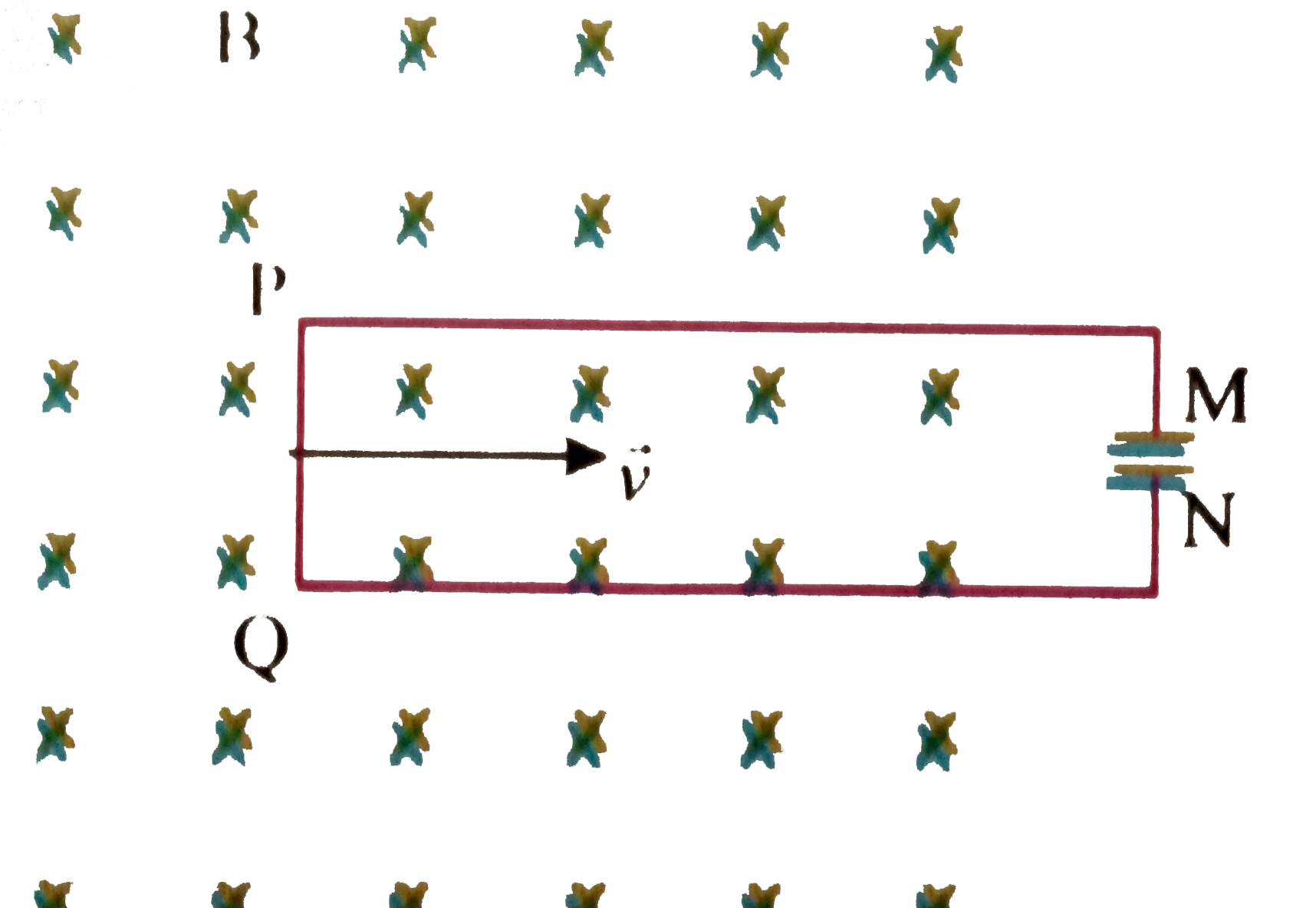
A rod PQ is connected to the capacitor plates. The rod is placed in a magnetic field (B) directed downwards perpendicular to the plane of the paper. If the rod is pulled out of magnetic field with velocity →v as shown in Figure.
 View Solution
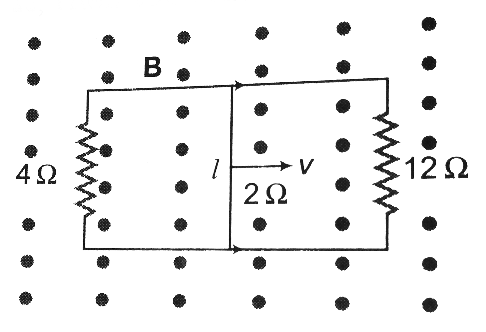
In the figure shown as uniform magnetic field |B|=0.5T is perpendicular to the plane of circuit. The sliding rod of length l=0.25m moves uniformly with constant speed v=4ms−1. If the resistance of the sllides is 2Ω, then the current flowing through the sliding rod is
 View Solution


