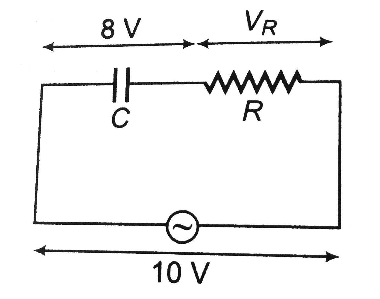
In a series CR circuit shown in the figure, the applied voltuge is 10V and the voltage across capacitor is found to be 8V. If the phase difference betweeni cutrent and the applied voltage will be tan−1(pq), then find pq.
'(##CEN_KSR_PHY_JEE_C24_E01_016_Q06##)'
The correct Answer is:12
Topper's Solved these Questions
Similar Questions
In a series CR circuit shown in figure,the applied voltage is 10V and the voltage across capacitor is found to be 8V
View SolutionIn a series C−R circuit shown in figureure, the applied voltage is 10V and the voltage across capacitor is found to8V. The voltage across R, and the phase difference between current and the applied voltage will respectively be
 .
.
View Solution
Knowledge Check
In a series C−R circuit shown in figureure, the applied voltage is 10V and the voltage across capacitor is found to8V. The voltage across R, and the phase difference between current and the applied voltage will respectively be
 .A6V,tan−1(43)B3V,tan−1(34)C6V,tan−1(34)Dnone of these
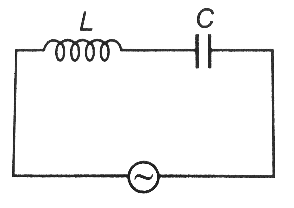
In a series L−C circuit, the applied voltage is V0. if omega is very low, then the voltage drop across the inductor VL and capacitor VC are
 .AVL=V02,VC=V02BVL=0,VC=V0CVL=V0,VC=0DVL=−VC=V02
In a series C−R circuit shown in figureure, the applied voltage is 10V and the voltage across capacitor is found to8V. The voltage across R, and the phase difference between current and the applied voltage will respectively be
 .
.
View SolutionIn a series L−C circuit, the applied voltage is V0. if omega is very low, then the voltage drop across the inductor VL and capacitor VC are
 .
.
View SolutionMaximum power loss (in watt) in the given circuit is
'(##CEN_KSR_PHY_JEE_C24_E01_020_Q10##)'
View SolutionIn an L-R circuit, an inductance of 0.1 H and a resistance of 1Ω are connected in series with an ac source of voltage V = 5 sin 10 t. The phase difference between the current and applied voltage will be
View SolutionIn an L-R circuit, an inductance of 0.1 H and a resistance of 1Ω are connected in series with an ac source of voltage V = 5 sin 10 t. The phase difference between the current and applied voltage will be
View SolutionIn a series LCR circuit, the voltage across an inductor, a capacitor and a resistor are 20 V, 20 V and 40 V, respectively. What is the phase difference between the applied voltage and the current in the circuit ?
View Solution
