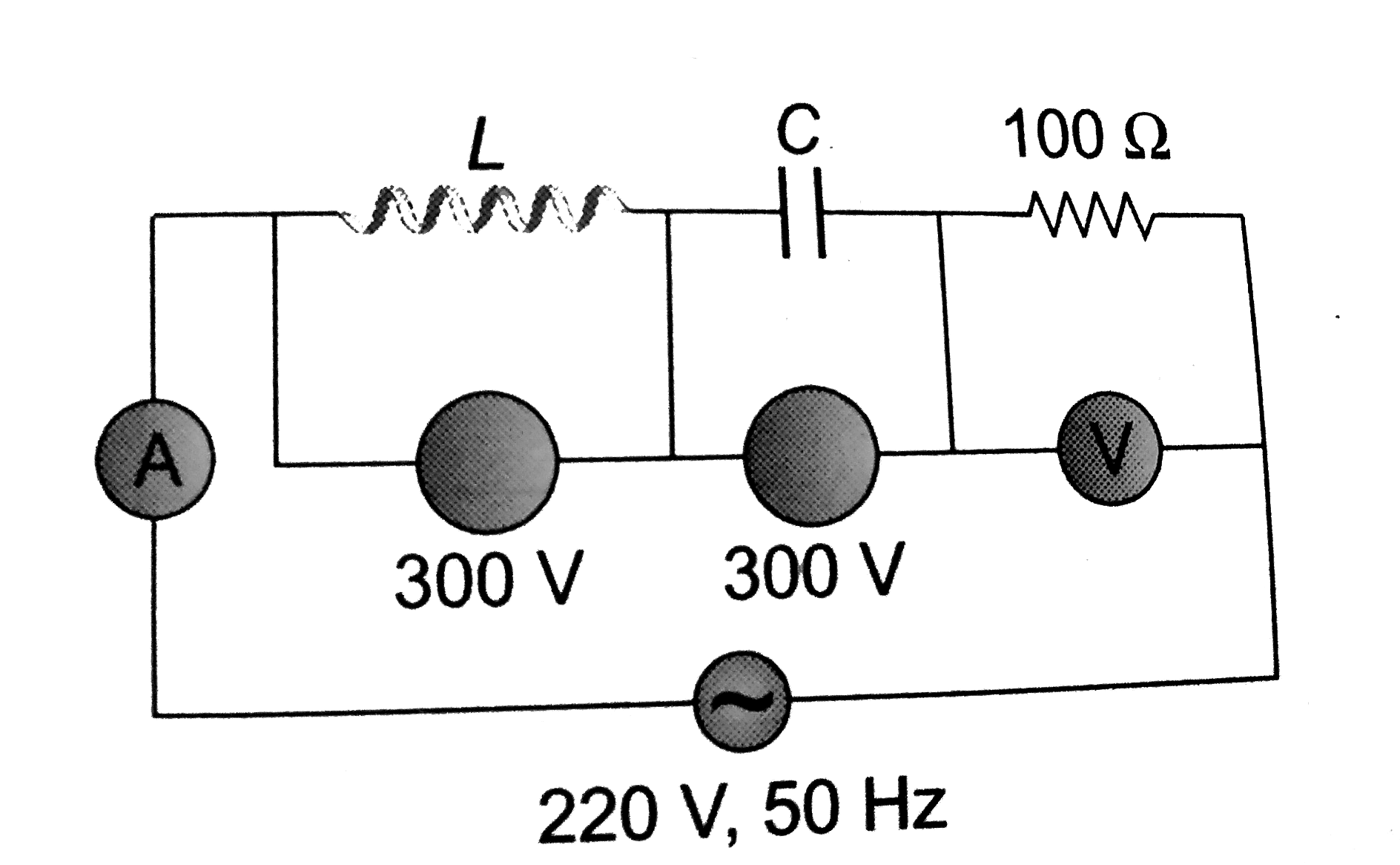
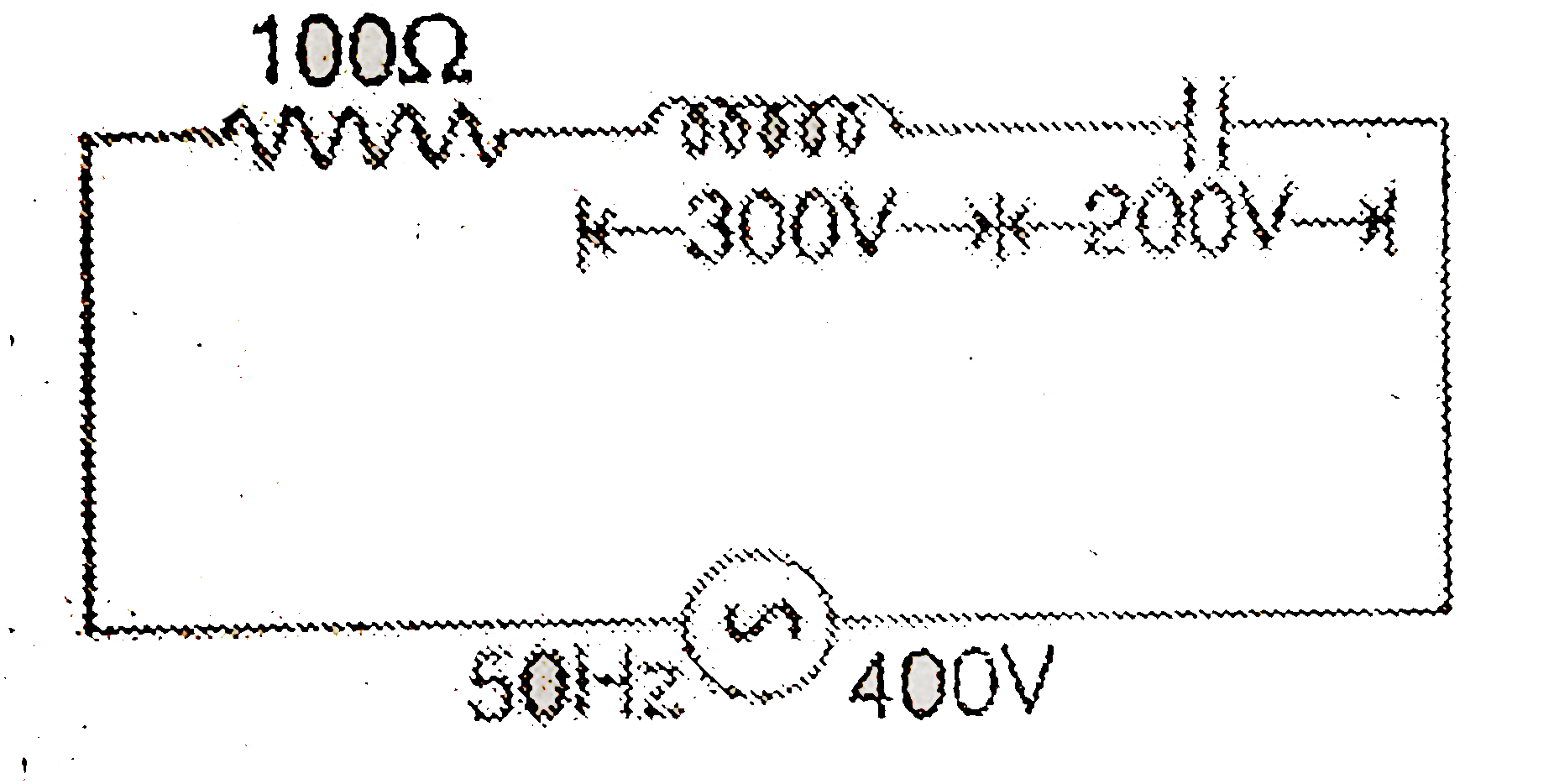
In the circuit shown in figure, what will be the reading of the voltmeter ?

300 V
900 V
200 V
400 V
The correct Answer is:C
Here, VL=VC=100V,V=200V
As V=√V2R+(VL−VC)2
∴200=√V2R+(100−100)2=VR or VR=200V
Topper's Solved these Questions
Similar Questions
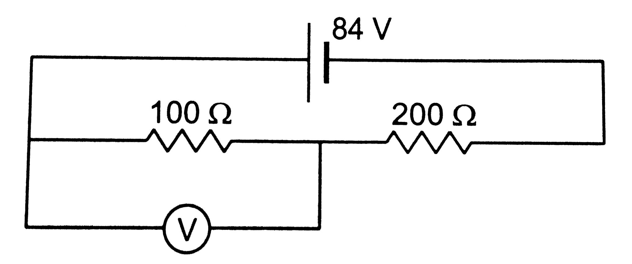
A voltmeter of resistances 400(Ω)is used to measure the potential difference across the 100(Ω)resistor in the circuit shown in figure.(a) What will be the reading of the voltmeter ?(b) What was the potential difference across 100(Ω)before the voltmeter was connected ?
View SolutionIn the circuit shown in figure, what will be the readings of voltmeter and ammeter?
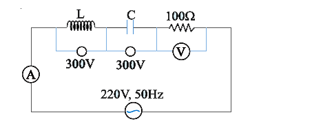
View SolutionIn the circuit shown below, what will be the reading of the voltmeter and ammeter?
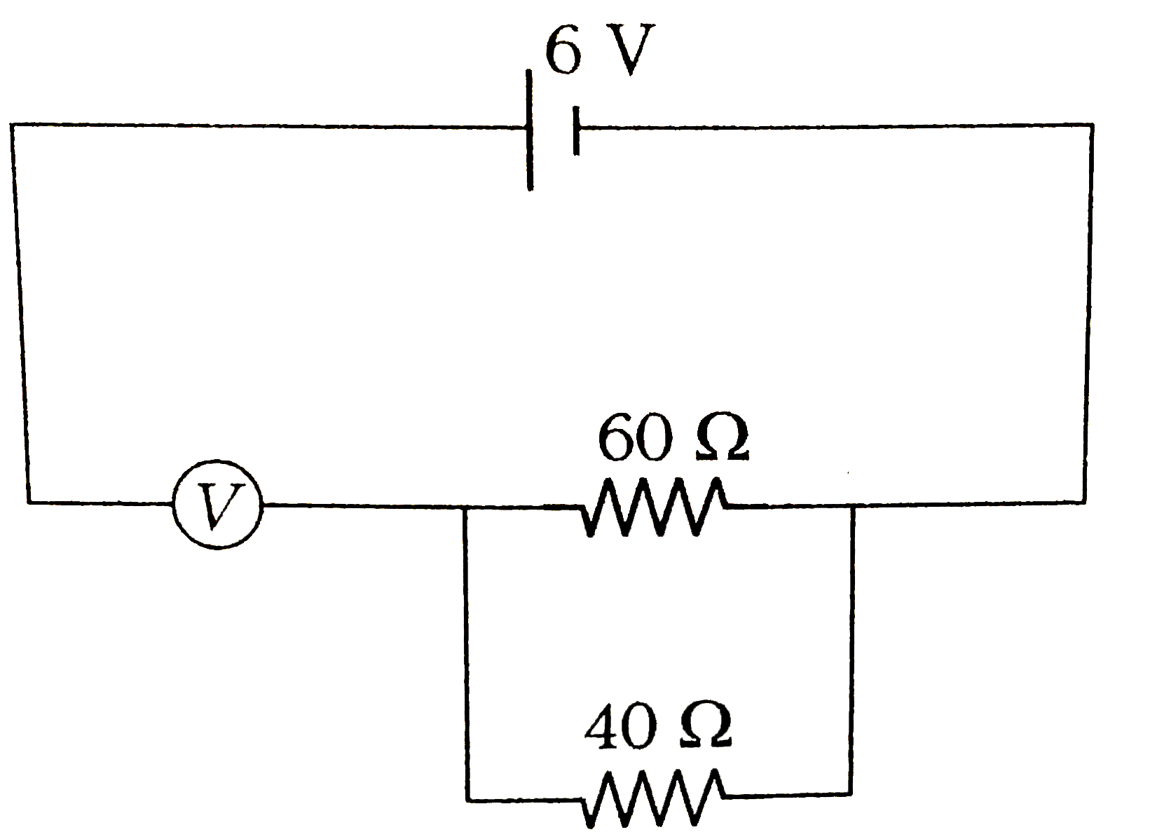
View SolutionIn the circuit shown in the figure, the voltmeter reading is
View SolutionAn ideal voltmeter V and ideal ammeter A are connected in a circuit as shown in the figure. If the reading of the voltmeter is 32 V, the reading of ammeter will be
View SolutionOn closing the switch S in the circuit as shown in the figure, the reading of the galvanometer G

View Solution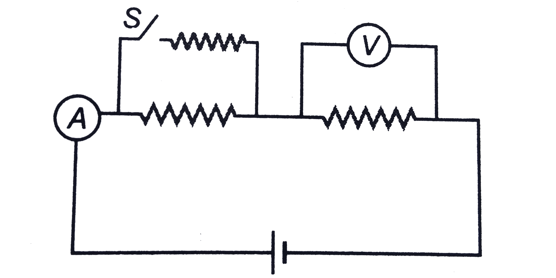
Assertion: In the circuit shown in figure after closing the switch S reading of ammeter will increase while that of voltmeter will decrease.
Reason : Net resistance decreases as parallel combination of resistors is increased,
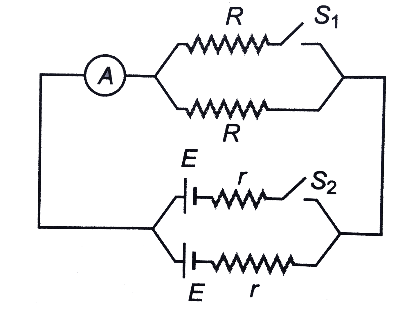
View SolutionIn the circuit shown in figure, reading of ammeter will
View SolutionIn the circuit shown in figure current in the circuit is
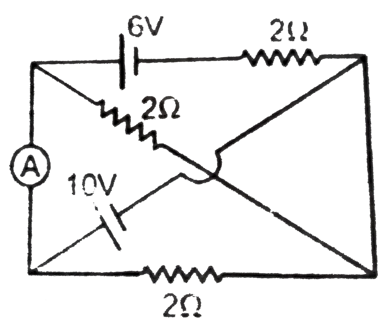
View SolutionAn ideal ammeter is connected in a circuit as shown in circuit diagram. What will be the reading of ammeter (in S.I units)
View Solution
