In the figure below, the switches S1andS2 are closed simultaneously at t=0 and a current starts to flow in the circuit. Both the batteries have the same magnitude of the electromotive force (emf) and the polarities are as indicated in the figure. Ignore mutual inductance between the inductors. The current ? in the middle wire reaches its maximum magnitude Imax at time t=τ. Which of the following statements is (are) true?
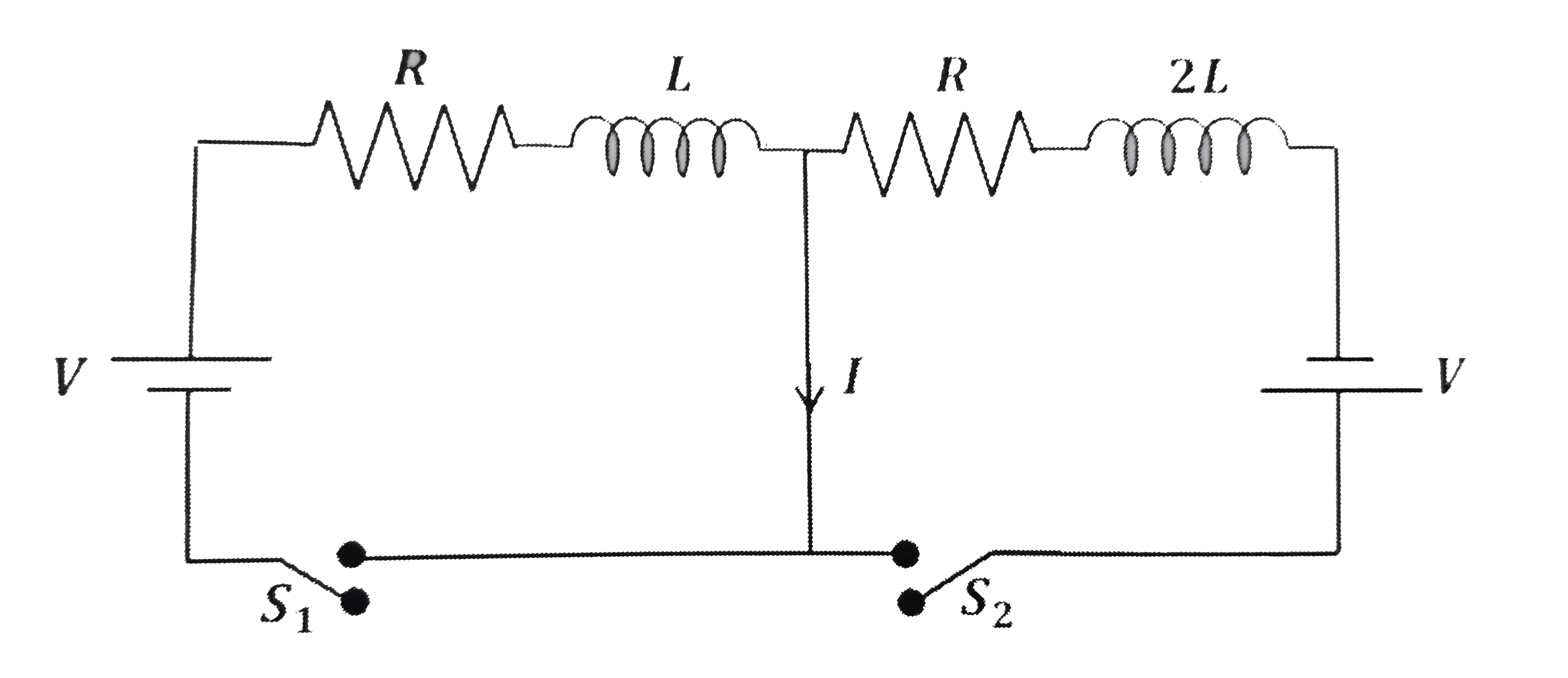
Imax=V2R
Imax=V4R
τ=LR In 2
τ=2LR In 2
Step by step video & image solution for In the figure below, the switches S_(1) and S_(2) are closed simultaneously at t =0 and a current starts to flow in the circuit. Both the batteries have the same magnitude of the electromotive force (emf) and the polarities are as indicated in the figure. Ignore mutual inductance between the inductors. The current ? in the middle wire reaches its maximum magnitude I_(max) at time t=tau. Which of the following statements is (are) true? by Physics experts to help you in doubts & scoring excellent marks in Class 12 exams.
Updated on:21/07/2023Topper's Solved these Questions
- JEE ADVANCEDBOOK - JEE ADVANCED PREVIOUS YEARCHAPTER - JEE ADVANCEDEXERCISE - SECTION 2
7 Videos
- JEE ADVANCEDBOOK - JEE ADVANCED PREVIOUS YEARCHAPTER - JEE ADVANCEDEXERCISE - SECTION 3 PARAGRAPH 3
3 Videos
- JEE ADVANCEDBOOK - JEE ADVANCED PREVIOUS YEARCHAPTER - JEE ADVANCEDEXERCISE - Part I : PHYSICS (Section 3)Paragraph 2
2 Videos
- JEE (ADVANCE) 2020BOOK - JEE ADVANCED PREVIOUS YEARCHAPTER - JEE (ADVANCE) 2020EXERCISE - SECTION 3
6 Videos
- JEE ADVANCED 2020BOOK - JEE ADVANCED PREVIOUS YEARCHAPTER - JEE ADVANCED 2020EXERCISE - SECTION-3
6 Videos
Similar Questions
In the given circuit, the switch S is closed at time t=0 then select the correct statement for current l in resistance PQ as shown in the figure
_PHY_E05_091_Q01.png)
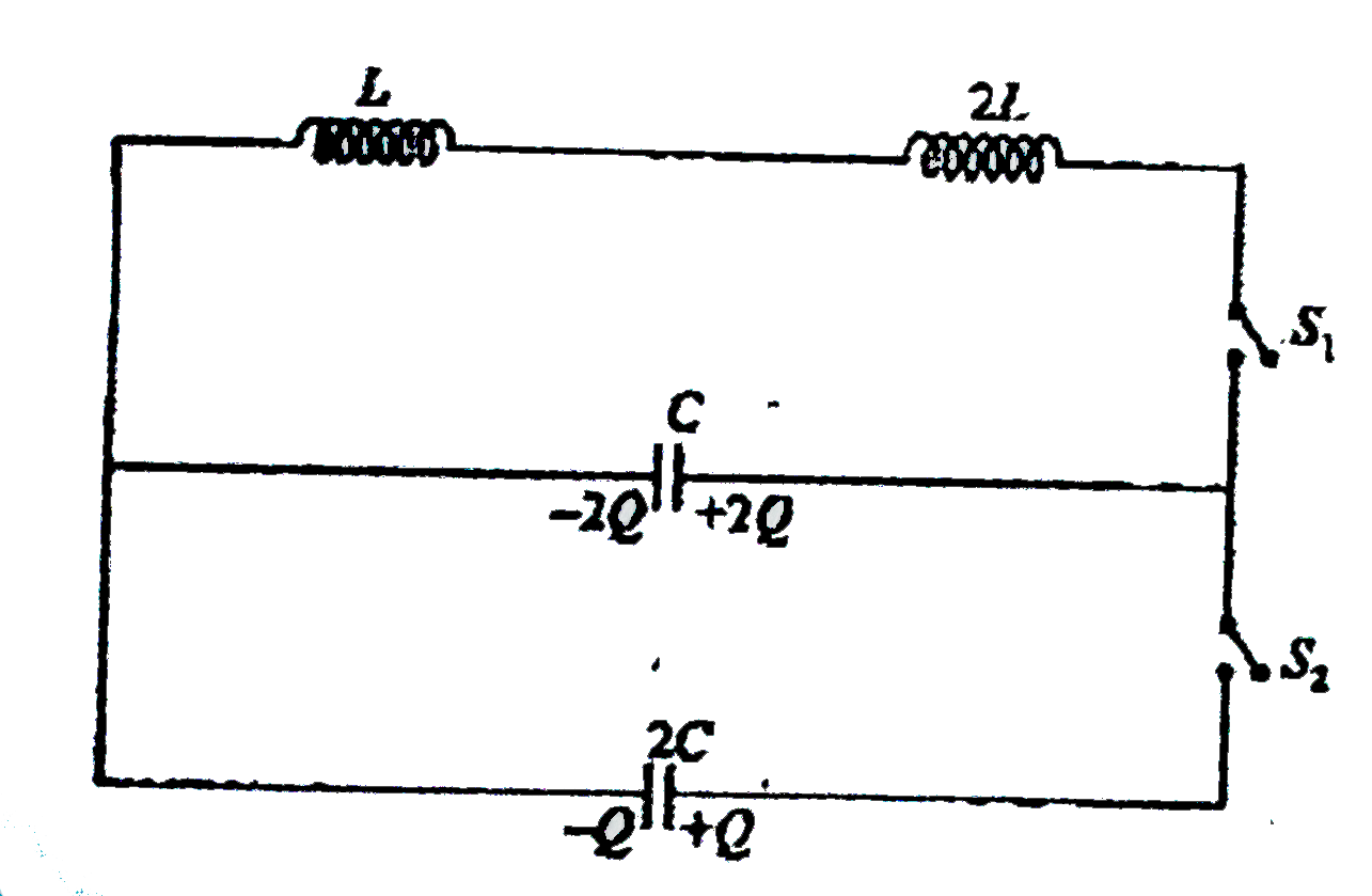
View SolutionIn circuit shown in figure-5.149 if switches S1 and S2 are closed at t=0, find the oscillation frequency of charge in this circuit. Neglect mutual induction between inductors.
View Solution
Knowledge Check
In the circuits (A) and (b) switches S1 and S2 are closed at t = 0 and are kept closed for a long time.The variation of current in the two circuits for t≥0 are roughly shown by figure (figures are schematic and not drawn to scale):
 A
A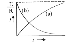 B
B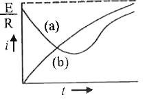 C
C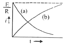 D
D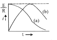
In the circuit shown, the switch 'S' is closed at t=0. Then the current through the battery steady state reached is
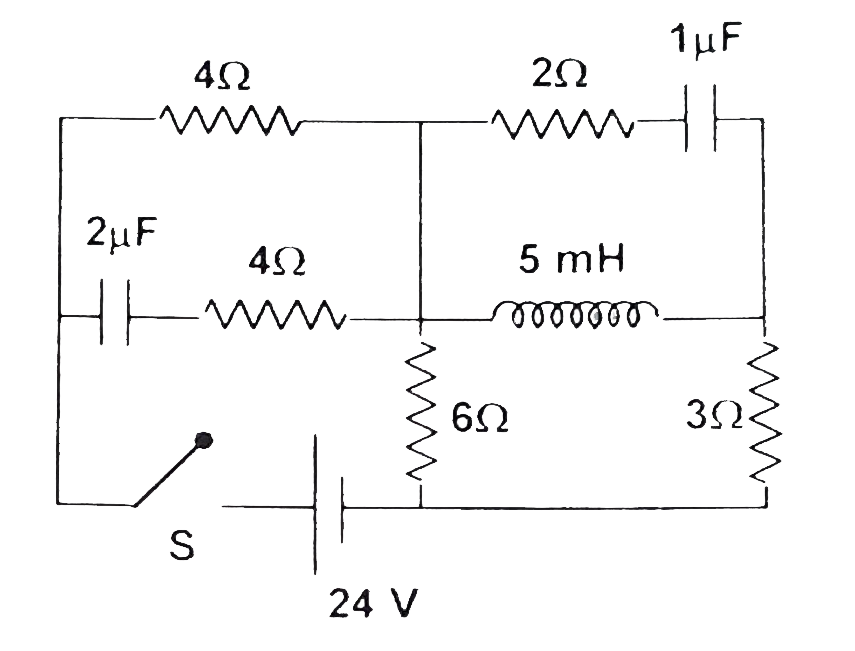 A2AB4AC6AD8A
A source of constant voltage V is connected to a resistance R and two ideal inductor L1andL2 through a switch S as shown. There is no mutual inducance between the two inductors. The swtich S is initially open. At t=0, the switch is closed and current begins to flow. Which of the following options is / are correct ?
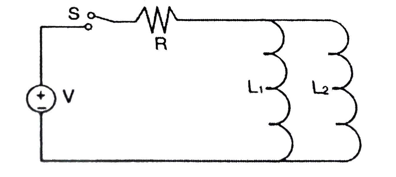 AAfter a long time, the current through L2 will be VRL1L1+L2BAt t=0, the current through the resistance R is VRCAfter a long time, the current through L1 will be VRL2L1+L2DThe ratio of the current through L1andL2 is fixed at all times (t>0)
In the given circuit, the switch S is closed at time t = 0, then select the correct statement for current l in resistance PQ as shown in the figure.
_PHY_E05_045_Q01.png)
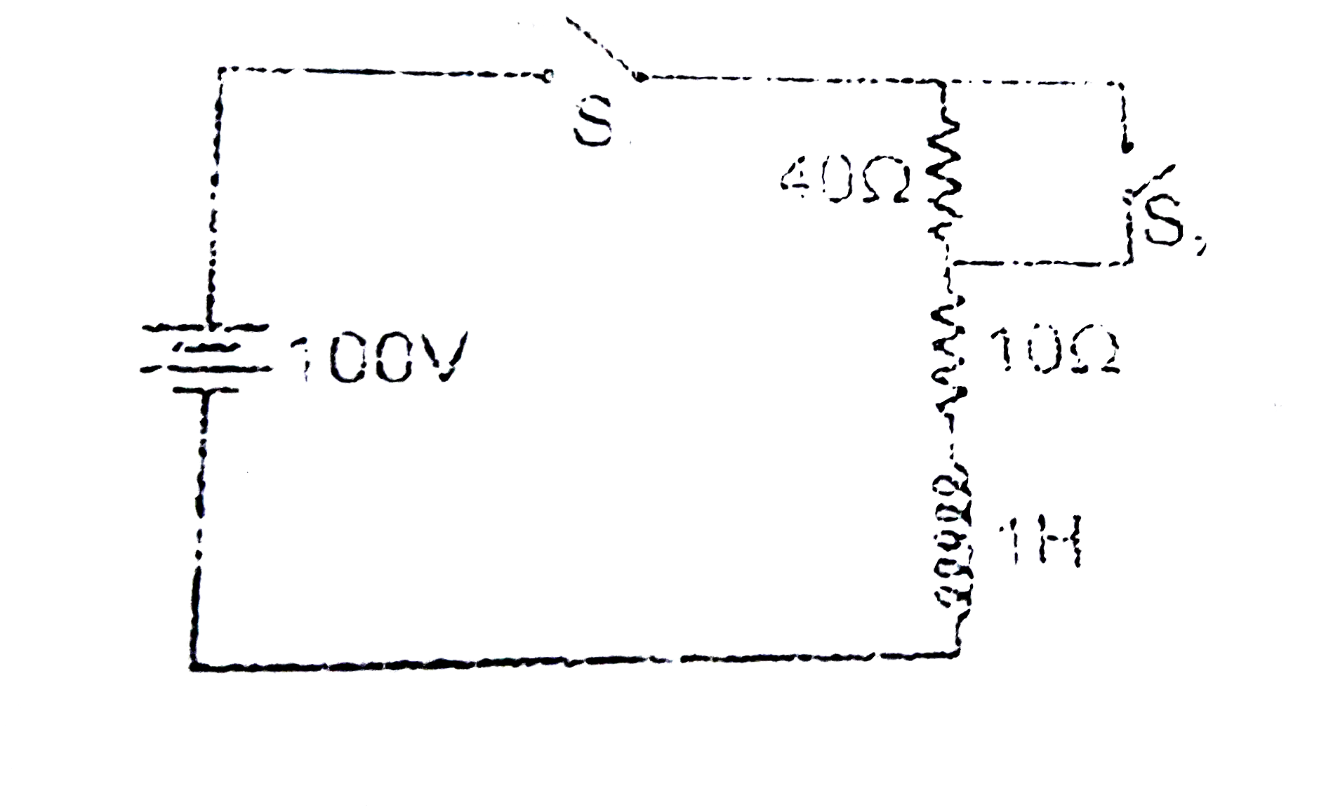
View SolutionIn the circuit diagram shown in the figure the switches S1 and S2 are closed at time t=0.After time t=(0.1)ln2sec, switch S2 is opened.The current in the circuit at time t=0.2n2sec is equal to x32amp.Find out value of x.
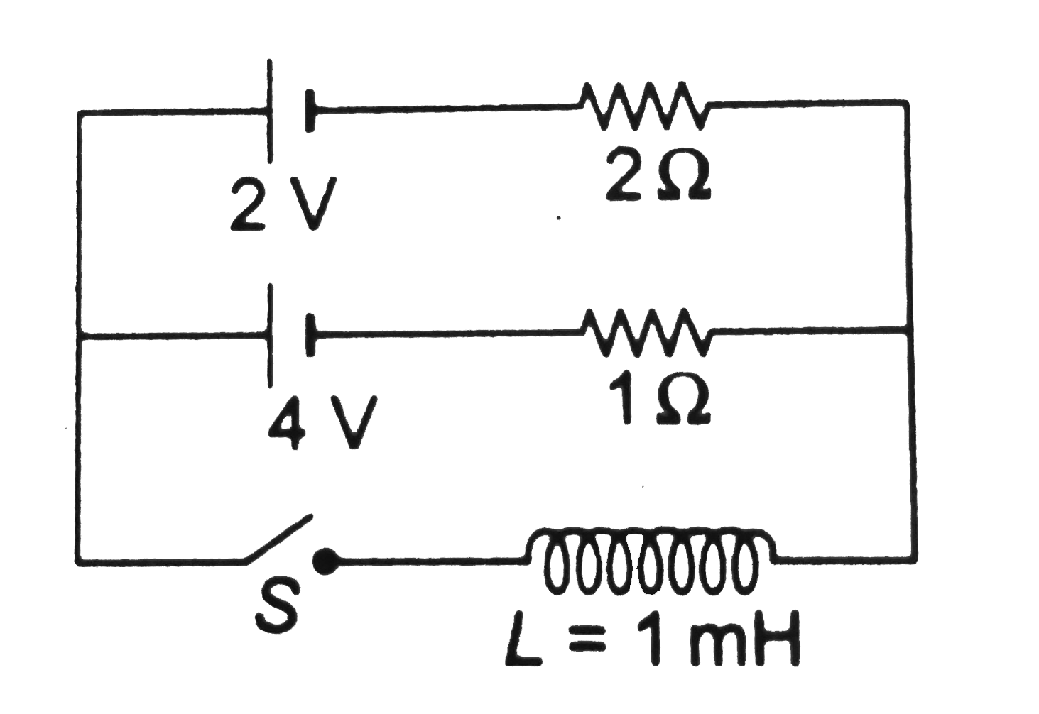
View SolutionIn the circuit shown, switch S is closed at time t=0. Find the current through the inductor as a function of time t.
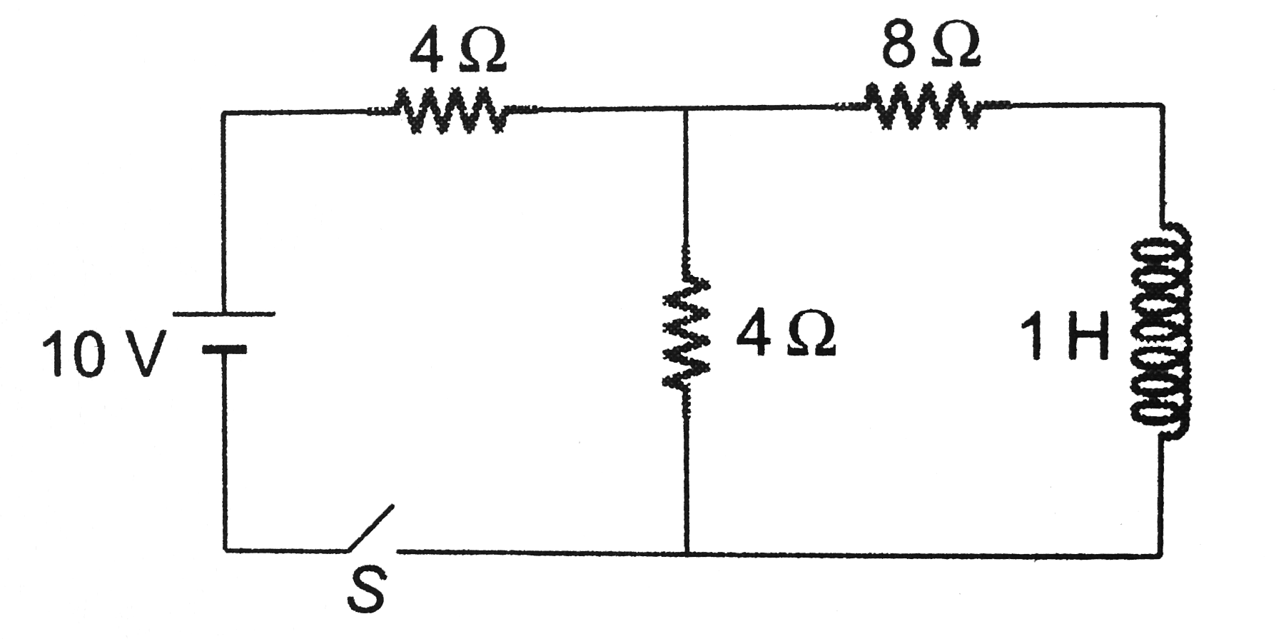
View SolutionThe switch in figure is closed at time t=0. Find the current in the inductor and the current through the switch as functions of time thereafter.
View SolutionSwitch S of the circuit shows in Fig is closed at t=0. If e denotes the induced emf in L and I is the current flowing through the circuit the circuit at time t, which of the following graphs is//are correct?

View Solution
