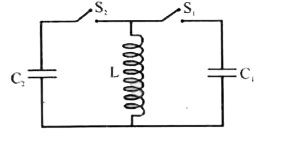
In the following circuit C1=900μF which is charged to a p.d of 100V and C2=100μF is an unchanged capacitor L = 10 henry . Explain how will you change C2 to a.p.d of 300V by adjusting the switched S1 and S2
 Solution in Tamil
Energy of C1=12C1V2=12×900×10−6×100×100
=4.5J
To charge C2 to a p.d. of 300 V, the energy needed =1/2C2V2
=1/2×100×10−6×300×300=4.5J
Now first close S1 and open S2 . allow the charge on C1 to discharge completely and the energy is stored in the inductor . this happens during the first 14 th of the period of oscillation
i.e., t1=T4=2π√LC14=0.15sec
upto 0.15 sec , S1 should be closed and S2 should be opened . Now close S2 and open S1 so that the inductor begins to discharge and C2 gets completely charged during the next 14th of period of oscillation .
i.e., t2=T4=2π√LC24=0.05sec
Upto 0.05 sec , S2 is to closed and S1is to be opened
Topper's Solved these Questions
- ALTERNATING CURRENT BOOK - NEW JOYTHI PUBLICATIONCHAPTER - ALTERNATING CURRENT EXERCISE - SOLUTIONS TO EXERCISES FROM NCERT TEST
24 Videos
- ALTERNATING CURRENT BOOK - NEW JOYTHI PUBLICATIONCHAPTER - ALTERNATING CURRENT EXERCISE - PRACTICE PROBLEMS FOR SELF ASSESSMENT
11 Videos
- ATOMSBOOK - NEW JOYTHI PUBLICATIONCHAPTER - ATOMSEXERCISE - COMPETITIVE EXAM CORNER
5 Videos
Similar Questions
A 100Ω resistor is connected to a 220 V , 50 Hz are supply .
a. What is the rms of current in the circuit ?
b. What is the net power consumed over a full cycle ?
View SolutionAn electric lamp runs at 120 V d.c and consumes 12 A. It is connected to 200 V, 50 Hz a.c. Find the inductance required and the power factor.
View SolutionThe set which represents the isotope , isobar, isotone respectively is
View SolutionFind the charges on the three capacitors connected to a bettery as shown in figure (31.E1). Take C1=2.0=2.0,μF,C2=4.0,μf,C3=6.0,μFandV=12vo<s.(31-E1). Take C1=2.0μF,C2=4.0μF,C2=6.0μFandV=12vo<s.
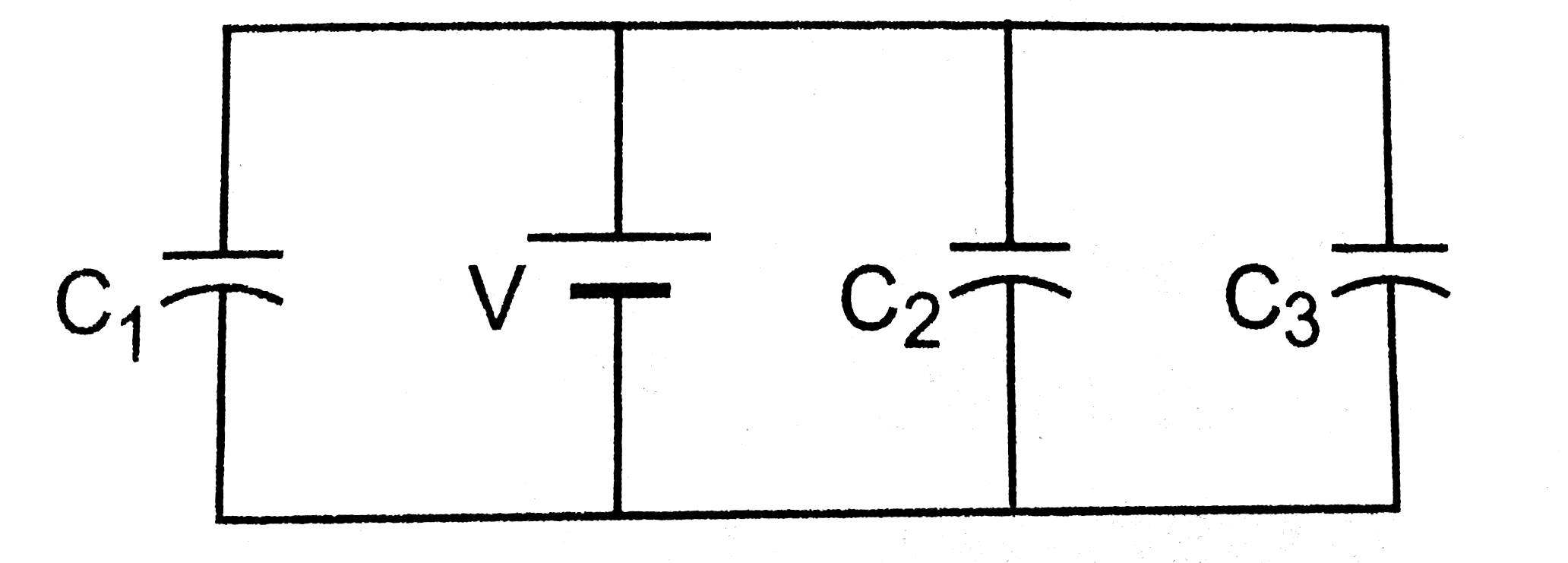
View SolutionFind the charges on the three capacitors connected to a bettery as shown in figure (31.E1). Take C1=2.0=2.0,μF,C2=4.0,μf,C3=6.0,μFandV=12vo<s.(31-E1). Take C1=2.0μF,C2=4.0μF,C2=6.0μFandV=12vo<s.
View SolutionThe capacitor C_1 in the figure shown initially carries a charge q_0 . When the switches S_1 and S_2 are closed,capacitor C_1 is connected in series to a resistor R and a second capacitor C_2 which is initially uncharged. The charge flown through wires as a function of time is where C=(C_1C_2)/(C_1+C_2)
View SolutionIn the given circuit C1=C,C2=2C,C3=3C. If charge at the capacitor C2 is Q. Then the charge at the capacitor C3 will be
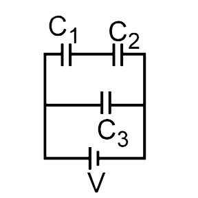
View SolutionIn the circuit shown the capacitors are C_1 = 15mu F , C_2 = 10 mu F and C_2 = 25 mu F . Find (i) The equivalent capacitance of the circuit (ii) The charge on each capacitor and (iii) The potential difference a across each capacitor.
View SolutionFind the charges on the three capacitors connected to a battery as shown in figure. Take C1=2.0μF,C2,=4.0μF,C3=6.0μF and V =10 volt
View SolutionTwo capacitorsC1=4μFandC2=2μF are charged to same potential V = 500 Volt, but with opposite polarity as shown in the figure. The switches S1andS2are closed.
View SolutionA capacitor of 30μ F charged to 100Vis connected in parallel to capacitor of 20μ F charged to 50V .The common potential is ...?
View Solutionतीन संधारित्र C1,C2 व C3 चित्रानुसार जुड़े हुए हैं। यदि C1= 2 μF, C2 = 3 μF तथा C3=5μF हो तो P व Q के बीच तुल्य धारिता क्या होगी ?

View Solutionचित्रानुसार परिपथ में, दो समानान्तर प्लेटों बाले संघारित्रों में प्रत्येक की धारिता C1 है। पारम्भ में स्विच S1 को दबामा जाता है ताकि संधारित्र C1 पूर्ण रूप से आवेशित हो जाए। इसके बाद S1 को छोड़ दिया जाता है। इसके पश्चात् संधारित्र C2 को आवेशित करने के लिए स्विच S2 को दबाया जाता है। कुछ समय के बाद S2 को छोड़ दिया जाता है तथा S3 को दबाया जाता है। कुछ समय बाद
View SolutionFigure 25-43 shows a 24.0 V battery and four uncharged capacitors of capacitances C1=1.00μF,C2=2.00μFC3=3.00μFandC4=4.00μF IF only switch S1 is closed, what is the charge, on (a) capacitor 1 (b) capacitor 2 (c ) capacitor 3 and (d) capacitor 4? IF both switches are enclosed , what is the charge on (e) capacitors1.(f) capacitor 2, (g) capacitor 3, and (h) capacitor 4?
View SolutionIn fig.25-45 V=12V C1=10μFandC2=C3=20μF Switch S in first thrown to the left side until capacitor 1 reaches equilibrium. Then the switch is thrown to the right when equilibrium is again reached, how must charge is on capacitor 1?
View Solution
