
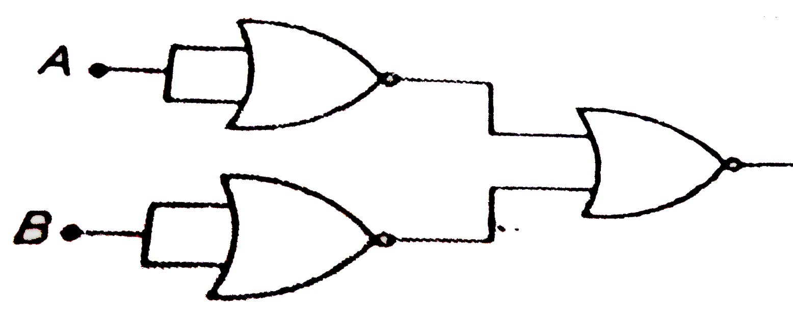
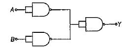
Name of gate obtained from the combination of gates shown in the figure. Draw its logic symbol. Write the truth table of the combination.
Video Solution
Text Solution
Logic gate. A logic gate is a digital circuit, which works according to some logical relationship between input and ouput voltages.
Nor Gate. When the output of OR gate is connected to the input of NOT gate we get a NOR gate as shown in figure (a) .

Logic symbol of NOR gate is shown in fig. (b).
Truth table. The truth table of NOR gate

|
Topper's Solved these Questions
- SOLIDS AND SEMICONDUCTOR DEVICESBOOK - MBD -HARYANA BOARDCHAPTER - SOLIDS AND SEMICONDUCTOR DEVICESEXERCISE - Long answer type questions
6 Videos
- SOLIDS AND SEMICONDUCTOR DEVICESBOOK - MBD -HARYANA BOARDCHAPTER - SOLIDS AND SEMICONDUCTOR DEVICESEXERCISE - Objective type questions
21 Videos
- SOLIDS AND SEMICONDUCTOR DEVICESBOOK - MBD -HARYANA BOARDCHAPTER - SOLIDS AND SEMICONDUCTOR DEVICESEXERCISE - Objective type questions
21 Videos
- PRINCIPLES OF COMMUNICATIONBOOK - MBD -HARYANA BOARDCHAPTER - PRINCIPLES OF COMMUNICATIONEXERCISE - Objective Type Questions
19 Videos
Similar Questions
Knowledge Check
The combination of the gates shown in the figure produces
 ANOR gateBOR gateCAND gateDXOR gate
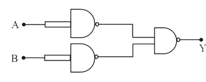
The combination of gates shown in the figure below produces
 ANOR gateBOR gateCAND gateDXOR gate
The combination of the gates shown in figure produces
 AAND gateBXOR gateCNOR gateDNAND gate
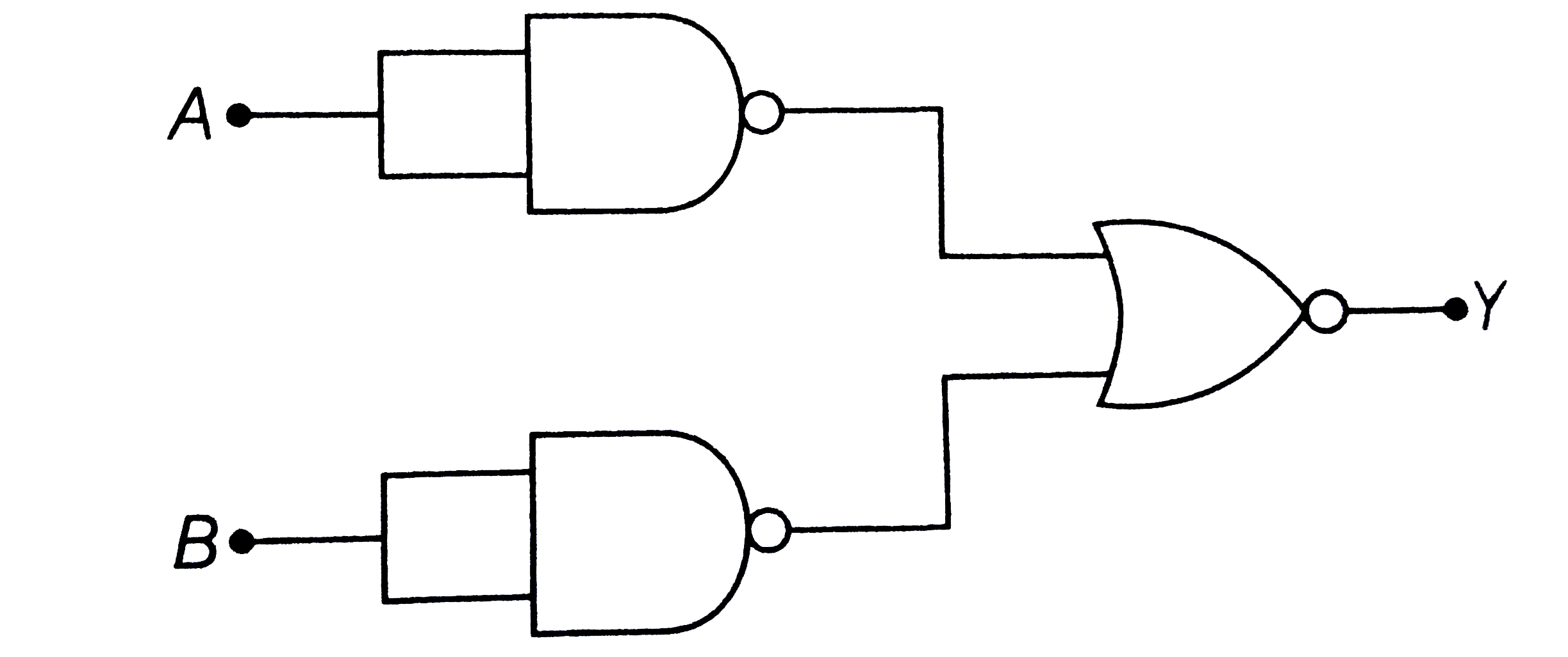
The combination of the gates shown in the figure results in
View SolutionThe combination of gates shown in the figure below produces .

View SolutionWrite the truth table of AND gate.
View SolutionThe combination of the gates shown in the figure below produces
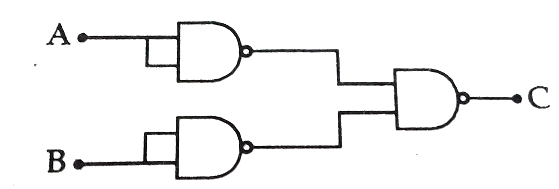
View SolutionThe combination of the gates shown in the figure below produces
View Solution

