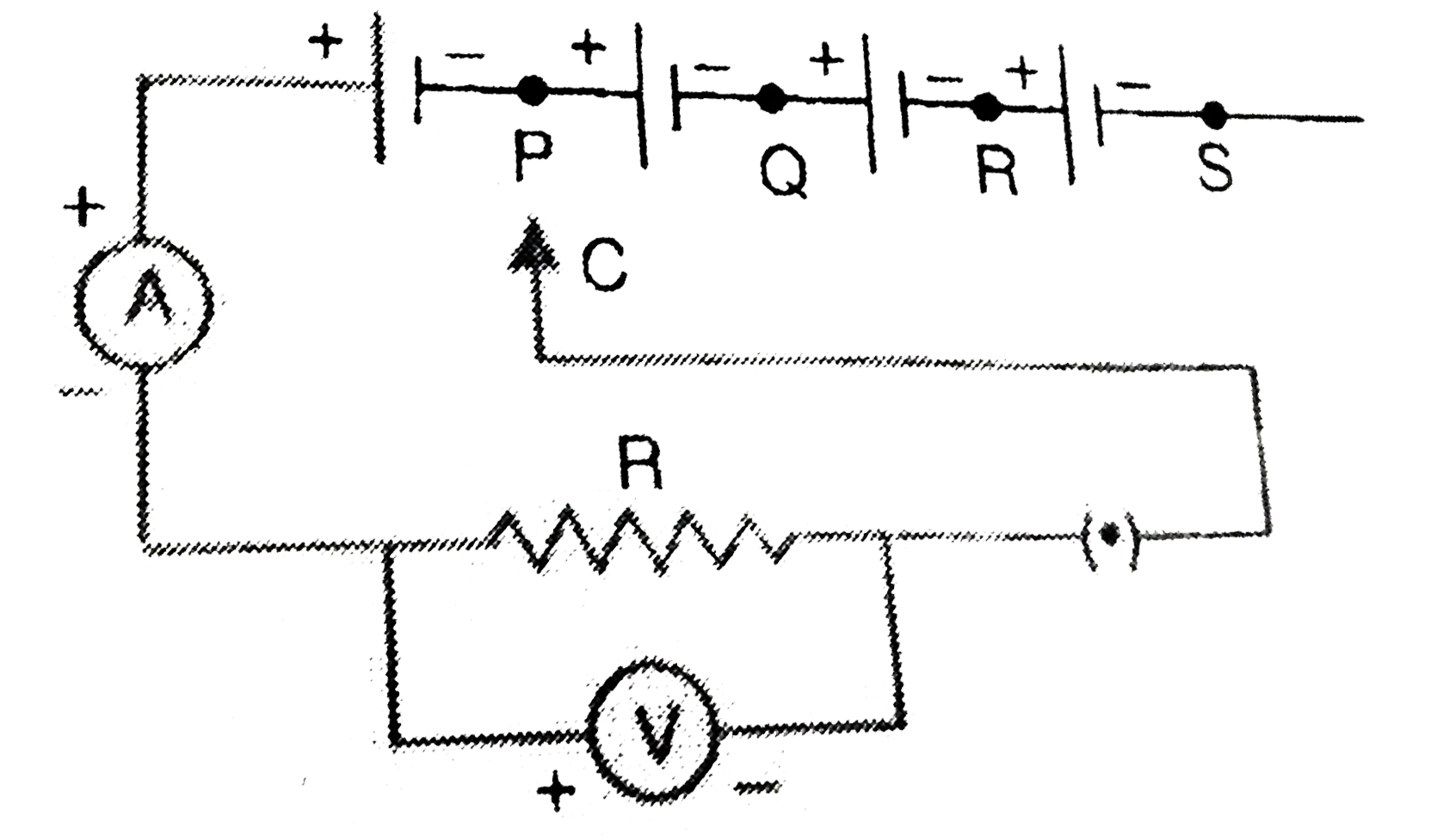
Which of the following is the correct set-up for studying the dependence of the current on the potential difference across a resistor and why?

A' is a correct set-up.
The ammeter must be connected in series between the battery and the resistor. The voltmeter should be put in parallel across the resistor. All the polarities must also be correct.
Set-up 'A' satisfies all these, so it is correct set-up.
Topper's Solved these Questions
- X BOARDSBOOK - X BOARDSCHAPTER - X BOARDSEXERCISE - SET II (SECTION -A
1 Videos
- X BOARDSBOOK - X BOARDSCHAPTER - X BOARDSEXERCISE - SET II (SECTION -B)
3 Videos
- X BOARDSBOOK - X BOARDSCHAPTER - X BOARDSEXERCISE - SET I (SECTION-D)
6 Videos
- SAMPLE QUESTION PAPER BOOK - X BOARDSCHAPTER - SAMPLE QUESTION PAPER EXERCISE - Section-B
11 Videos
Similar Questions
Knowledge Check
The following four circuits have been made for studying the dependence of current on the potential difference across a resistor.
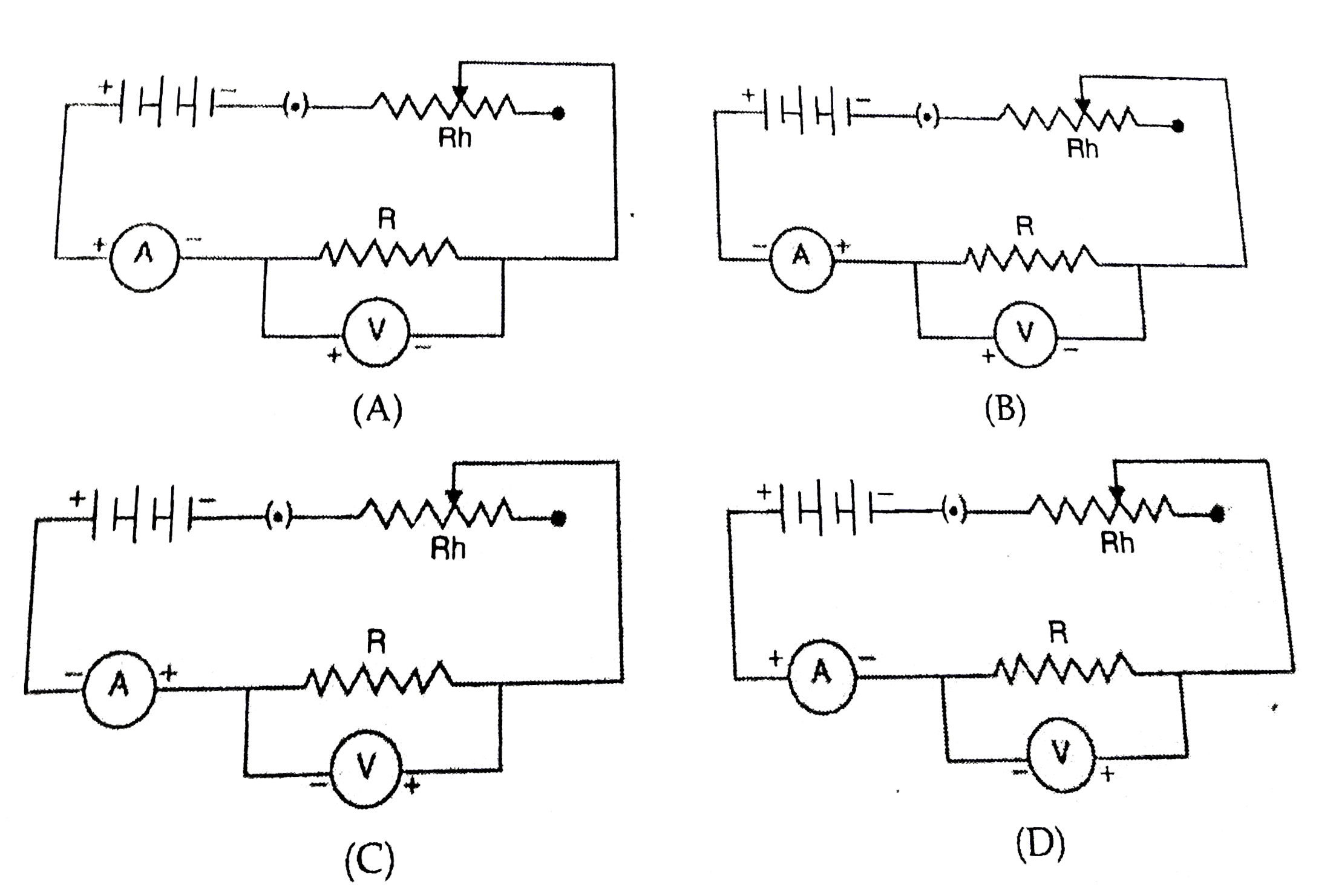
The correct circuit is :AABBCCDDConsider the following circuits diagrams drawn by four students :
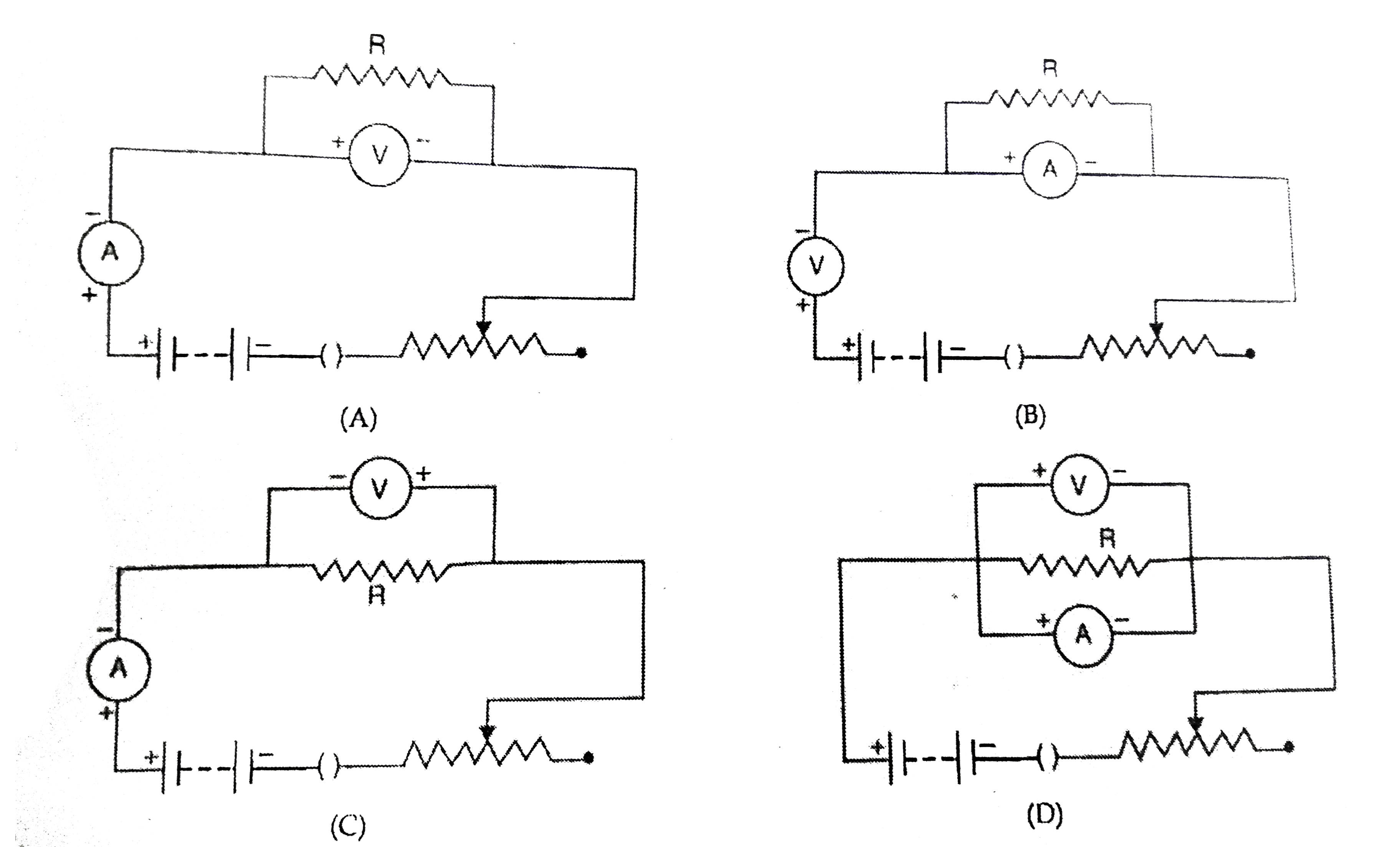
The correct circuit diagram for studying the dependence of current on the potential difference across a resistor is :AABBCCDDYou are given tha following four voltmeters to study the dependence of current (I) on the potential difference (V) across a resistor.

Which one of the above voltmeters would you prefer to use in the circuit to begin your experiment ?AABBCCDD
Draw a labelled circuit diagram to study the dependence of current (I) on the potential
difference (V) across a resistor.
View SolutionThe potential difference across the 3 resistor shown in figure is
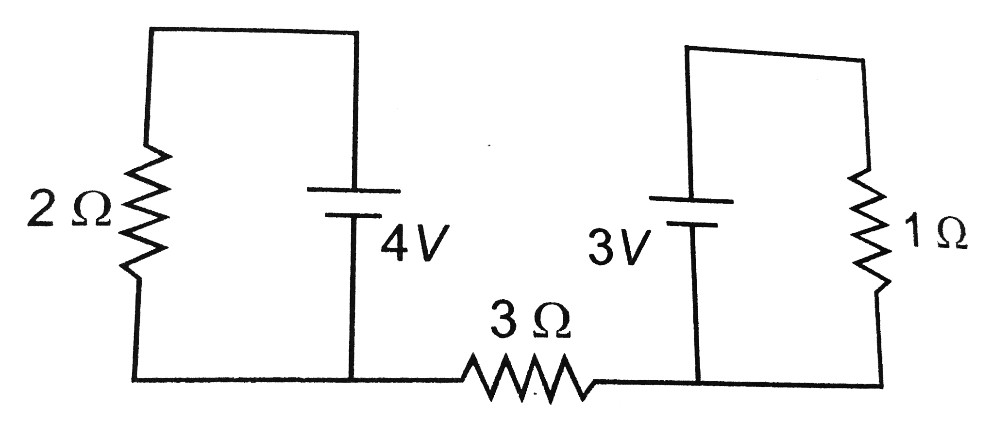
View SolutionWhat is the potential difference across resistor in the given circuit ?
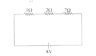
View SolutionGraphs plotted by four students A, B, C and D for the experiment "To study the dependence of current (I) on the potential difference (V) across a resistor" are shown below :

The correct V-I graph is :
View SolutionA student used the set up given here to study the dependence of current (I) on the potential difference (V) across a resistor.
He kept the contact C in four different positions marked as P,Q,R and S in the figure. On calculating the values of the ratio VI for his four readings, he would find that the value of this ratio :
View Solution
