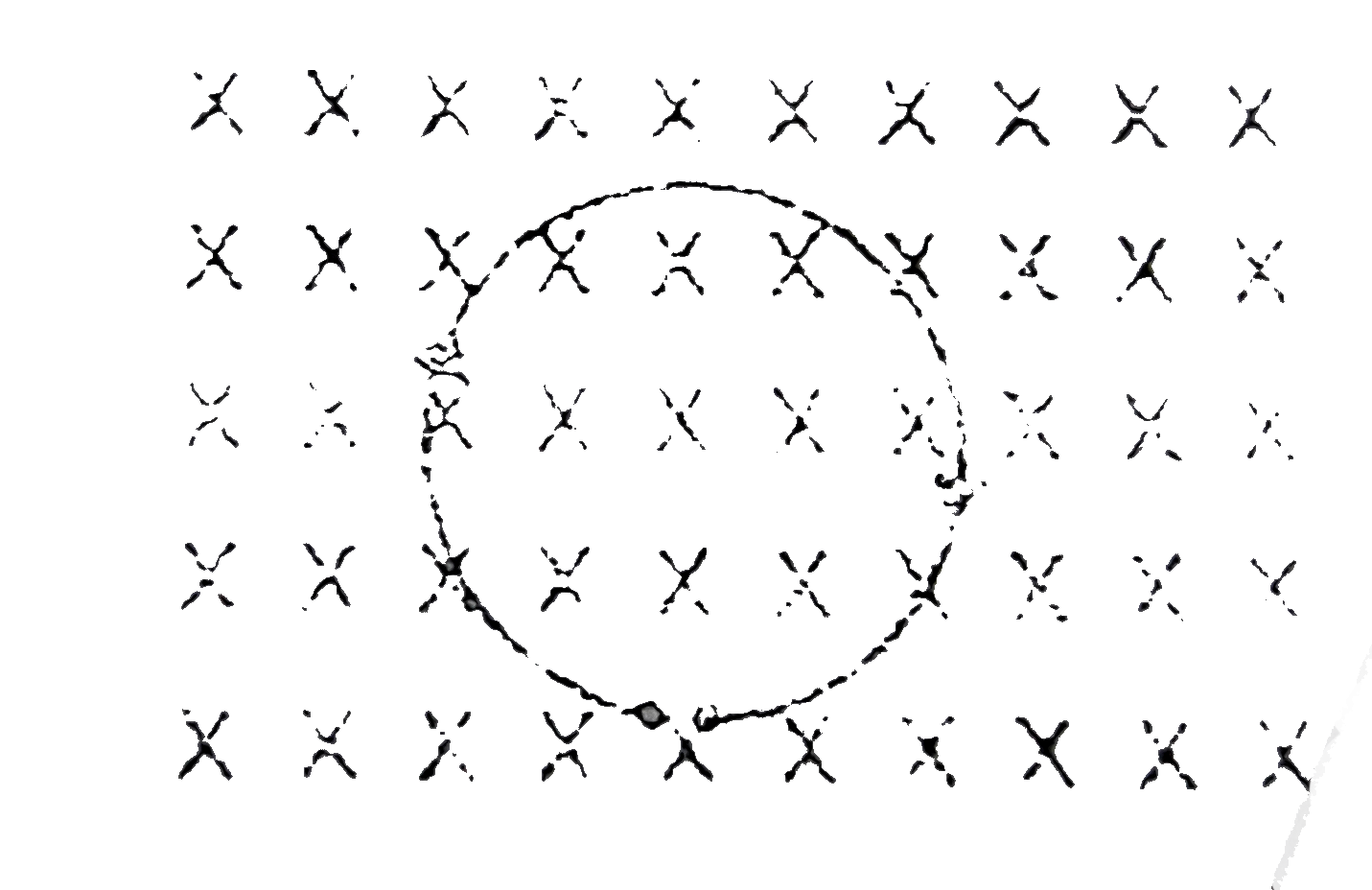
A thin flexible wire of length L is connected to two adjacent fixed points carries a current I in the clockwise direction, as shown in the figure.When system is put in a uniform magnetic field of strength B going into the plane of paper, the wire takes the shape of a circle.The tension in the wire is:
A
IBL
B
IBLπ
C
IBL2π
D
IBL4π
Video Solution
Text Solution
The correct Answer is:C
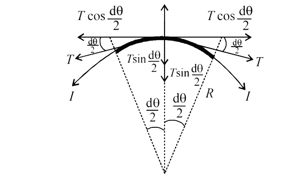
Let us consider an elemental length dl subtending an angle dθ at the centre of the circle. Let FBbethe3mag≠ticforceact∈gonthis≤n>h.Then<br>F_(B) = BI(dl) directedupwardsasshown<br> = BI(Rd theta) { because angle(d theta = (arc(dl))/(radius R)]<br> = (BI(L))/(2 pi) d theta [ because 2 pi R = L rArr R = (L)/(2 pi)]<br>Let Tbethetension∈thewireact∈galong⊥hendsofthee≤mental≤n>hasshown.Onresolv∈g T,wef∈dtˆthecompo≠nts. T cos ((d theta)/(2)) cancel out and the components . T sin ((d theta)/(2))addup→balanceF_(B).<br>Atequilibrium 2 T sin ((d theta)/(2)) = BI (L)/(2 pi) d theta<br>⇒ 2 T(d theta)/(2) = BI(L)/(2 pi) d theta [∵dθ2=small]
rArr = (BIL)/(2 pi)
|
Updated on:21/07/2023
Related Playlists
- BOOK - SUNIL BATRA (41 YEARS IITJEE PHYSICS)CHAPTER - MOVING CHARGES AND MAGNETISMEXERCISE - MCQs(d )1videos
MOVING CHARGES AND MAGNETISM
- BOOK - SUNIL BATRA (41 YEARS IITJEE PHYSICS)CHAPTER - MODERN PHYSICSEXERCISE - MCQ (One Correct Answer1videos
MODERN PHYSICS
- BOOK - SUNIL BATRA (41 YEARS IITJEE PHYSICS)CHAPTER - RAY AND WAVE OPTICSEXERCISE - JEE Main And Advanced209videos
RAY AND WAVE OPTICS
Similar Practice Problems
- Question 1 - Select One
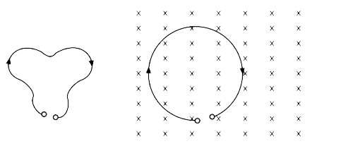
A thin flexible wire of length L is connected to two adjacent fixed points and carries a current I in the clockwise direction, as shown in the figure. When the system is put in a uniform magnetic field of strength B going into the plane of the paper, the wire takes the shape of a circle. The tension in the wire is :
 AIBLBIBLπCIBL2πDIBL4π
 - Question 1 - Select One
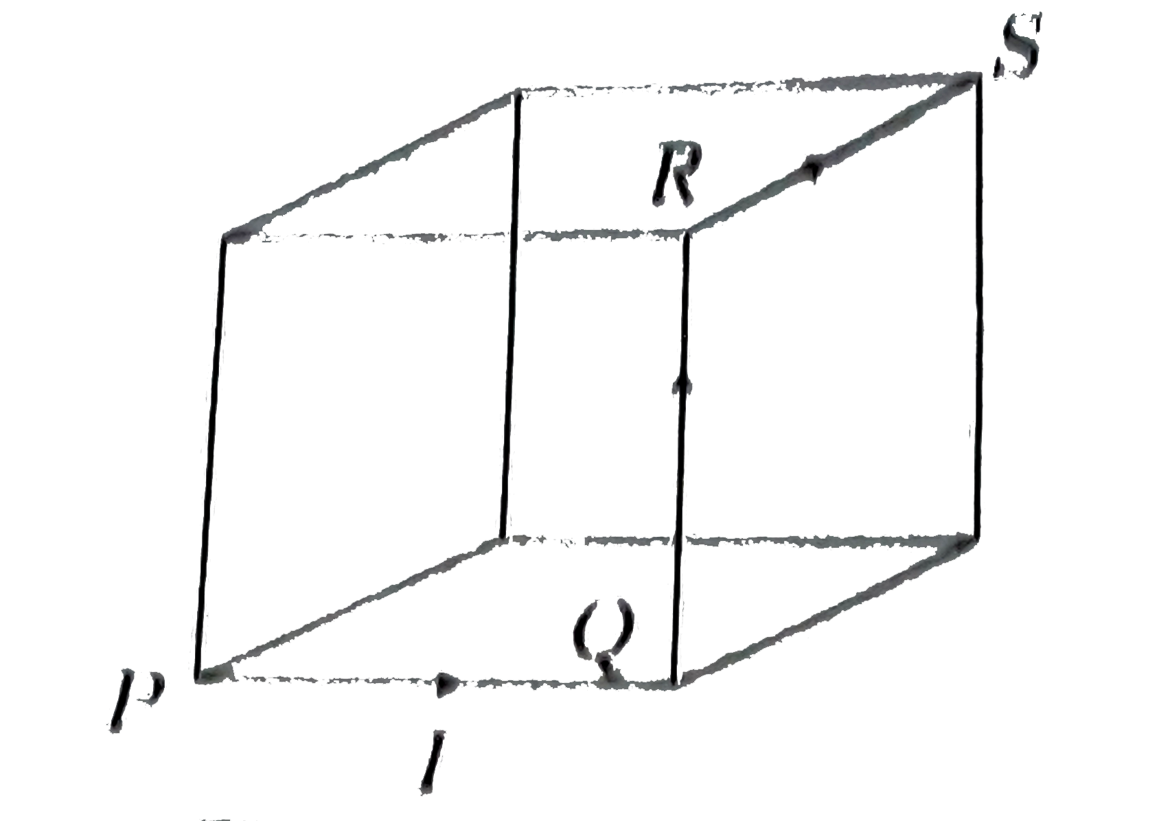
A wires PQRS carrying a current I runs along three edges of a cube of side l as shown in figure. There exists a uniform magnetic field of magnitude B along one of the sides of cube. The magnitude of the force acting on the wire is
 AzeroB√3IBC√2IlBD2Ilb
 - Question 1 - Select One
Two infinitely long wires each carrying current I along the same direction are made into the geometry as shown in the figure. The magnetic field at the point P is
 Aμ0IπrBμ0Ir(1π+14)CZeroDμ0I2πr
 - Question 1 - Select One
A long wire carrying current 'I' is bent into the shape as shown in the figure. The net magnetic field intensity at the centre 'O' is
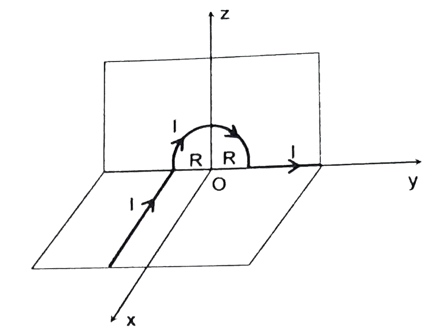 Aμ0I4πR√1+π2Bμ0I4πR√2+π2Cμ0I4πR√4+π2Dμ0I4πR√9+π2
 - Question 1 - Select One
The magnetic field strength at a point P distant r due to an infinite straight wire carrying a current i is as shown in the figure
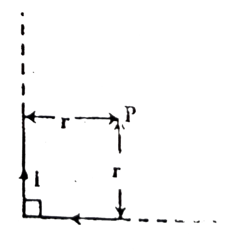 Aμ0Bμ0i/2√2rC(μ0i/√2πr)Dμ0i4πr[2+√2]
 - Question 1 - Select One
one of the two infinitely long wires carrying current I is bent as shown in the adjacent figure. The magnetic induction at C is equal to
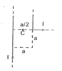 AzeroBμ0I2πaC3μ0I4πaDμ0Iπa
 - Question 1 - Select One
A conducting wire is moving towards right in a magnetic field B. The direction of induced current in the wire is shown in the figure. The direction of magnetic field will be
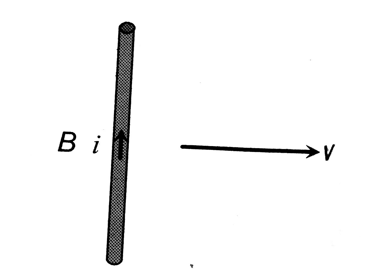 AIn the plane of paper pointing towards rightBIn the plane of paper pointing towards leftCperpendicular to the plane of paper and downwardsDperpendicular to the plane of paper and upwards
Similar Questions
A thin flexible wire of length L is connected to two adjacent fixed points and carries a current I in the clockwise direction, as shown in the figure. When the system is put in a uniform magnetic field of strength B going into the plane of the paper, the wire takes the shape of a circle. The tension in the wire is :
 View Solution
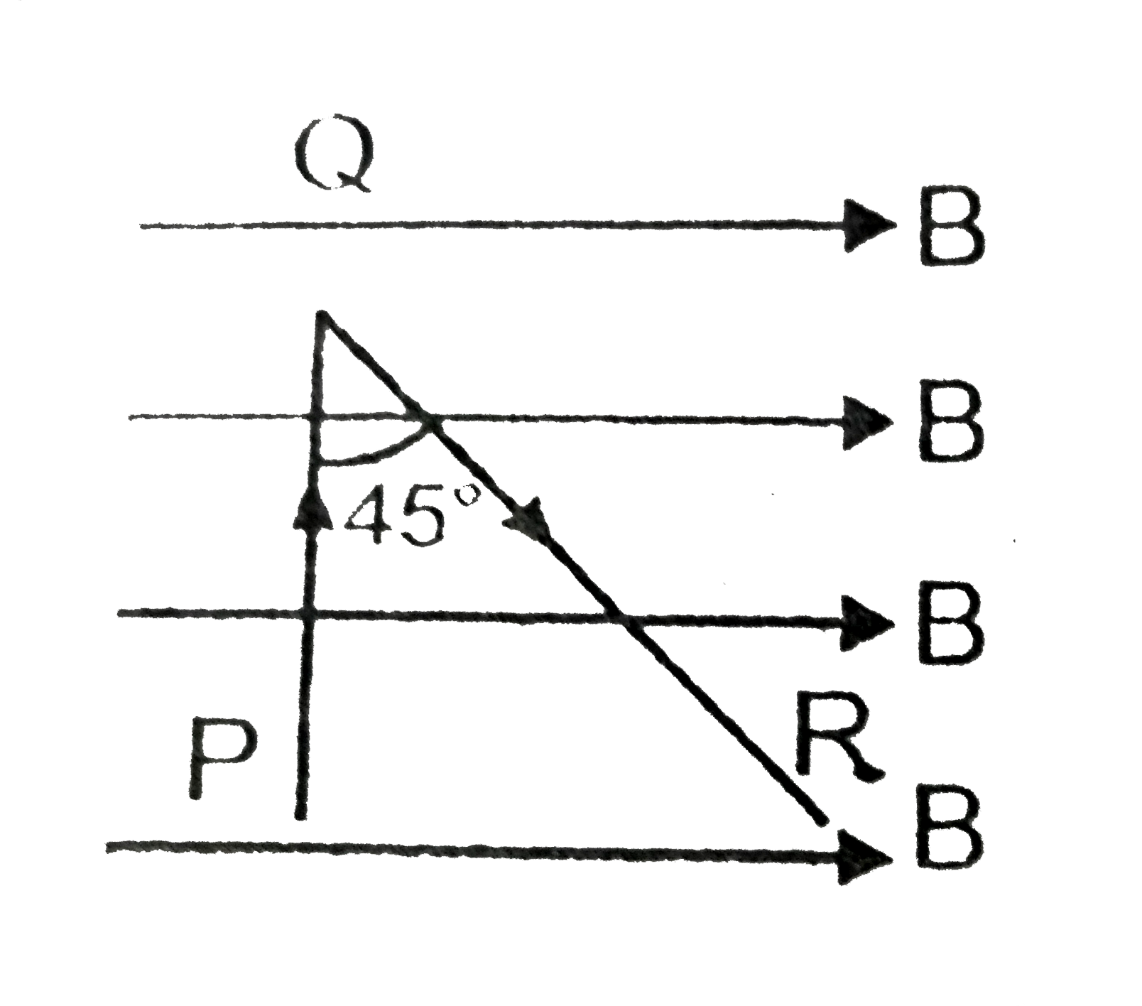
A wire PQR carrying a current l is bent as shown in the figure. It is placed in a uniform magnetic field B. What is the ratio of magnitude of the force on PQ to that on QR ?
 View Solution
A conducting wire carrying current I is shown in the figure. The magnitude of magnetic field at the point P will be
 View Solution

