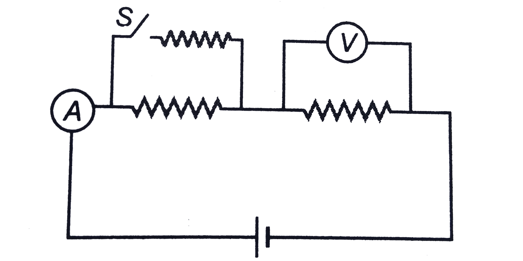
Assertion: In the circuit shown in figure after closing the switch S reading of ammeter will increase while that of voltmeter will decrease.
Reason : Net resistance decreases as parallel combination of resistors is increased,
If both Assertion and Reason are true and the Reason is correct explanation of the Assertion.
If both Assertion and Reason are true but Reason is not the correct explanation of Assertion.
If Assertion is true, but the Reason is false.
If Assertion is false but the Reason is true.
The correct Answer is:D
Since net resistance decreases, therefore main current increases Hence, net potential difference across voltmeter also increases.
Related Playlists
- BOOK - DC PANDEYCHAPTER - CURRENT ELECTRICITYEXERCISE - Level 1 Objective40videos
CURRENT ELECTRICITY
- BOOK - DC PANDEYCHAPTER - CURRENT ELECTRICITYEXERCISE - OBJECTIVE_TYPE1videos
CURRENT ELECTRICITY
- BOOK - DC PANDEYCHAPTER - CURRENT ELECTRICITYEXERCISE - Exercise 23.132videos
CURRENT ELECTRICITY
- BOOK - DC PANDEYCHAPTER - COMMUNICATION SYSTEMEXERCISE - Subjective11videos
COMMUNICATION SYSTEM
- BOOK - DC PANDEYCHAPTER - ELECTROMAGNETIC INDUCTIONEXERCISE - Medical entrances gallery25videos
ELECTROMAGNETIC INDUCTION
Similar Practice Problems
- Question 1 - Select One
In the circuit shown in figure, what will be the readings of voltmeter and ammeter?
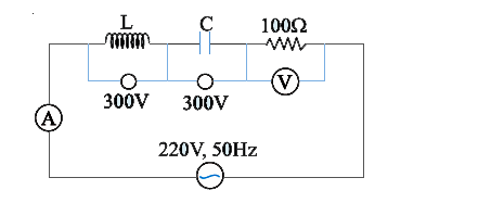 A800 V, 2 AB220 V, 2.2 AC300 V, 2 AD100 V, 2 A
 - Question 1 - Select One

Assertion : In the circuit shown in figure ammeter and voltmeter are non-ideal. Why positions of ammeter and voltmeter are changed, reading of ammeter will increase while of voltmeter will decrease.
Reason : Resistance of an ideal ammeter is zero while that of an ideal voltmeter is infinite.AIf both Assertion and Reason are true and the Reason is correct explanation of the Assertion.BIf both Assertion and Reason are true but Reason is not the correct explanation of Assertion.CIf Assertion is true, but the Reason is false.DIf Assertion is false but the Reason is true. - Question 1 - Select One
In the circuit shown in figure when the frequency of oscillator is increased, the reading of ammeter A4 is same as that of ammeter.
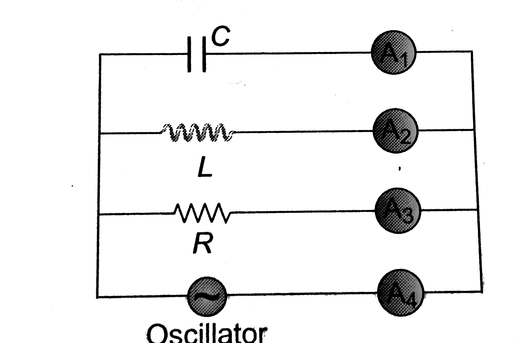 AA1BA2CA3DA1 and A2
 - Question 1 - Select One
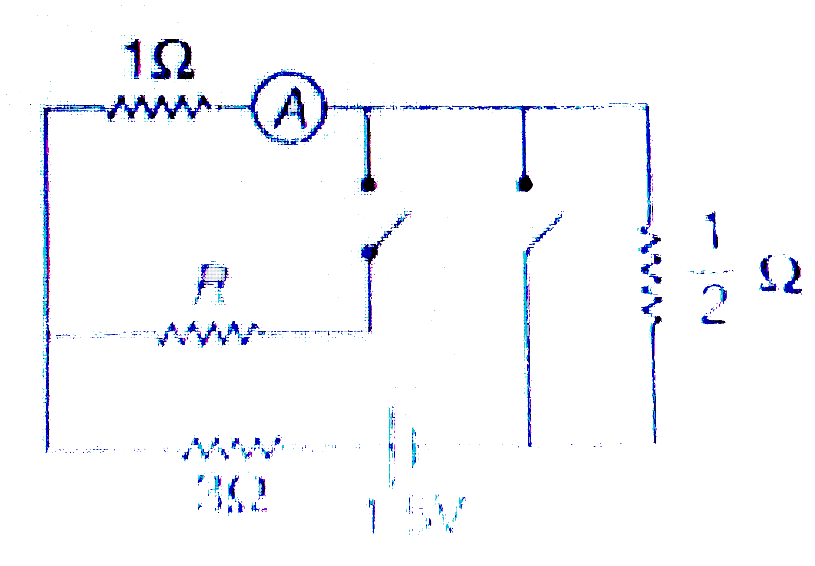
In the circuit shown in figure the reading of ammeter is the same with both switches open as with both closed. Then find the resistance R. (ammeter is ideal).
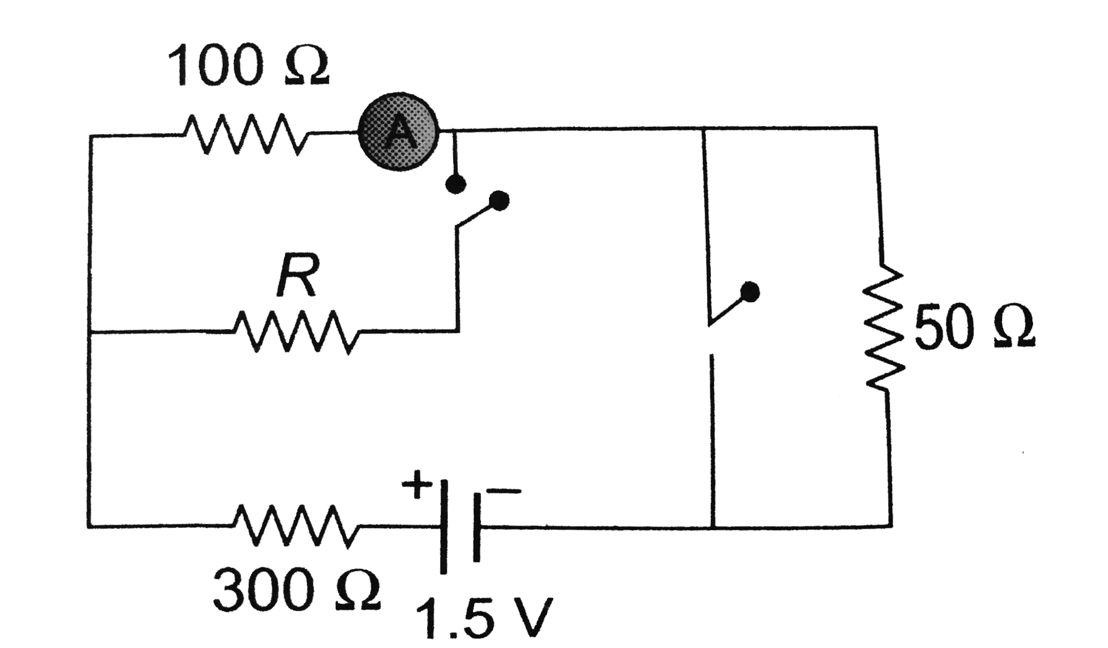 A550ΩB400ΩC350ΩD600Ω
 - Question 1 - Select One or More
In the circuit as shown in figure the switch is closed at t=0.
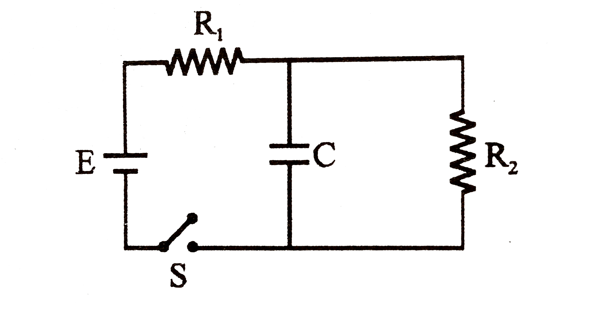
A long time after closing the switchAvoltage drop across the capacitor is EBcurent through the battery is E/R1+R2Cenegru stores in the capacitor is
12C(R2ER1+R2)2Dcurrent through the capacitor becomes zero - Question 1 - Select One
In the circuit shown in figure neglecting source resistance the voltmeter and ammeter reading will respectively, will be
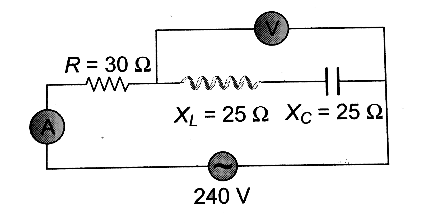 A0V,3AB150V,3AC150V,6AD0V,8A
Similar Questions
(a) Why does resistance increase in a series combination of resistors ?
(b) Why does resistance decrease in a parallel combination of resistors ?View SolutionIn the circuit as shown in figure , the reading of ammeter (ideal) in the same with both switches one and both switches closed. Find the resistance R ( in Ω)
 View Solution
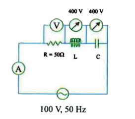
In the series LCR circuit as shown in the figure, the voltmeter V and ammeter A reading are
 View Solution
In the series LCR circuit as shown in the figure, the voltmeter V and ammeter A reading are
 View Solution

