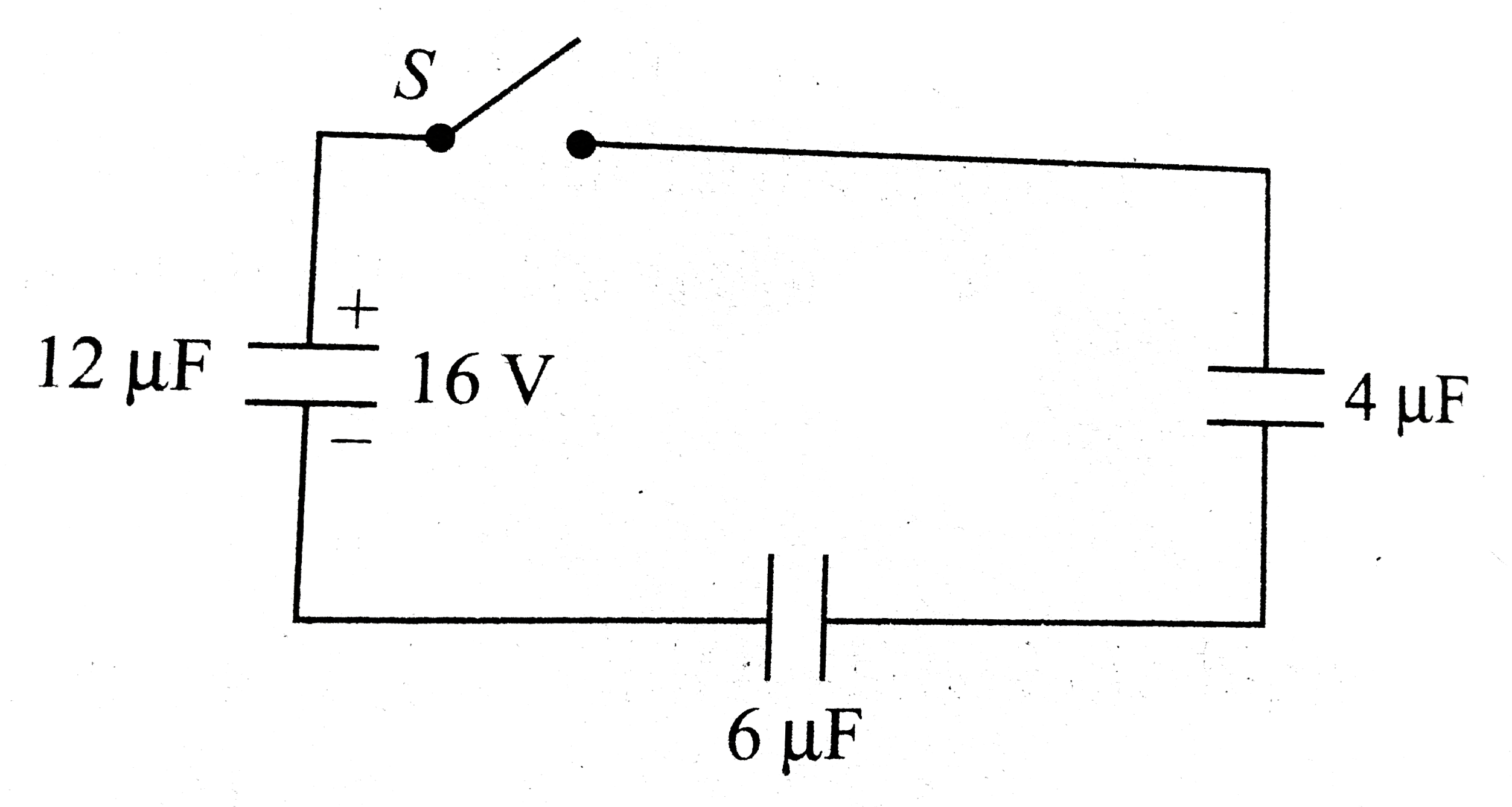
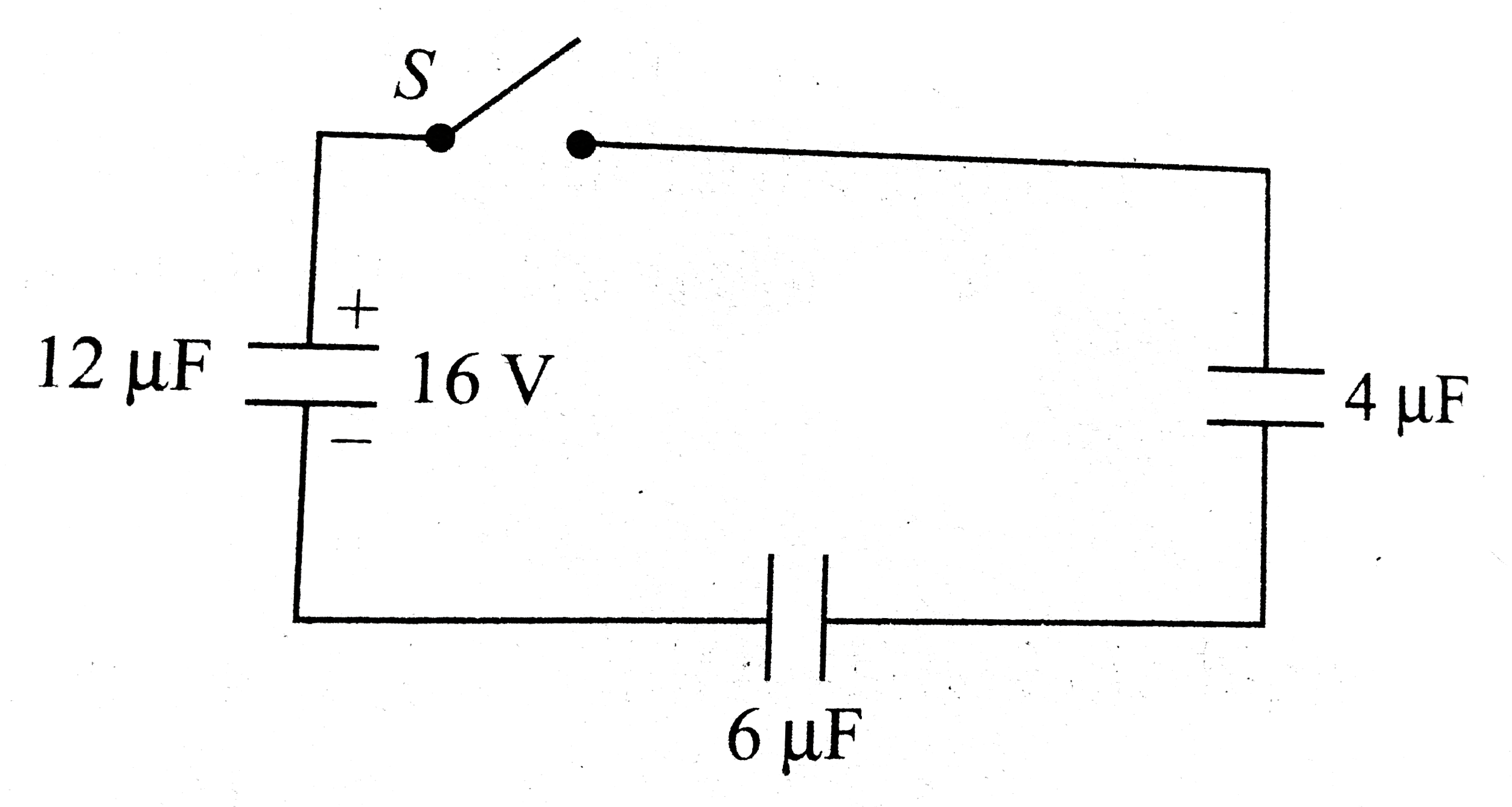
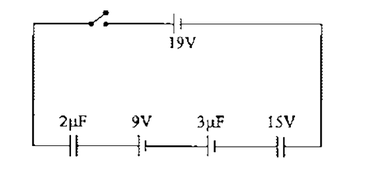
In the arrangement shown in, When the switch S is closed, find
 .
.
the final potential difference across the capacitor.
A
B
C
D
Video Solution
Text Solution
The correct Answer is:A
In the close loop,
 .
.
Potential defferece across
Potential defferece across .
|
Updated on:21/07/2023
Related Playlists
- BOOK - CENGAGE PHYSICSCHAPTER - CAPACITOR AND CAPACITANCEEXERCISE - Integer5videos
CAPACITOR AND CAPACITANCE
- BOOK - CENGAGE PHYSICSCHAPTER - CAPACITOR AND CAPACITANCEEXERCISE - Multile Correct11videos
CAPACITOR AND CAPACITANCE
- BOOK - CENGAGE PHYSICSCHAPTER - ATOMSEXERCISE - QUESTION BANK40videos
ATOMS
- BOOK - CENGAGE PHYSICSCHAPTER - CENGAGE PHYSICS DPPEXERCISE - subjective type51videos
CENGAGE PHYSICS DPP
Knowledge Check
- Question 1 - Select One
In the arrangement shown in, When the switch S is closed, find
 .
.
the final potential difference across the 12μF capacitor.A403VB203VC12VD24V - Question 1 - Select One
In the arrangement shown in , the switch S is find
 the final potential difference across the 4μF capacitorA12VB8VC20VD32V
 - Question 1 - Select One
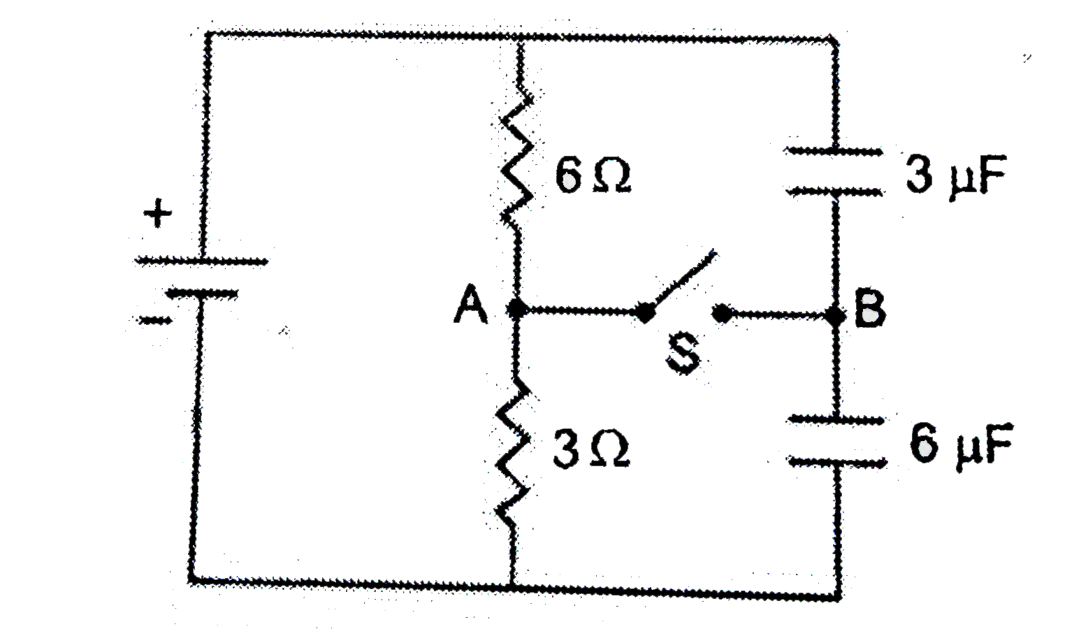
In the circuit shown above, when then switch S is closed,Ano charge flows through SBcharge flows from A to BCcharge flows from B to ADcharge flows initially from A to B and later from B to A - Question 1 - Select One
In the arrangement shown in in the switch S is , find
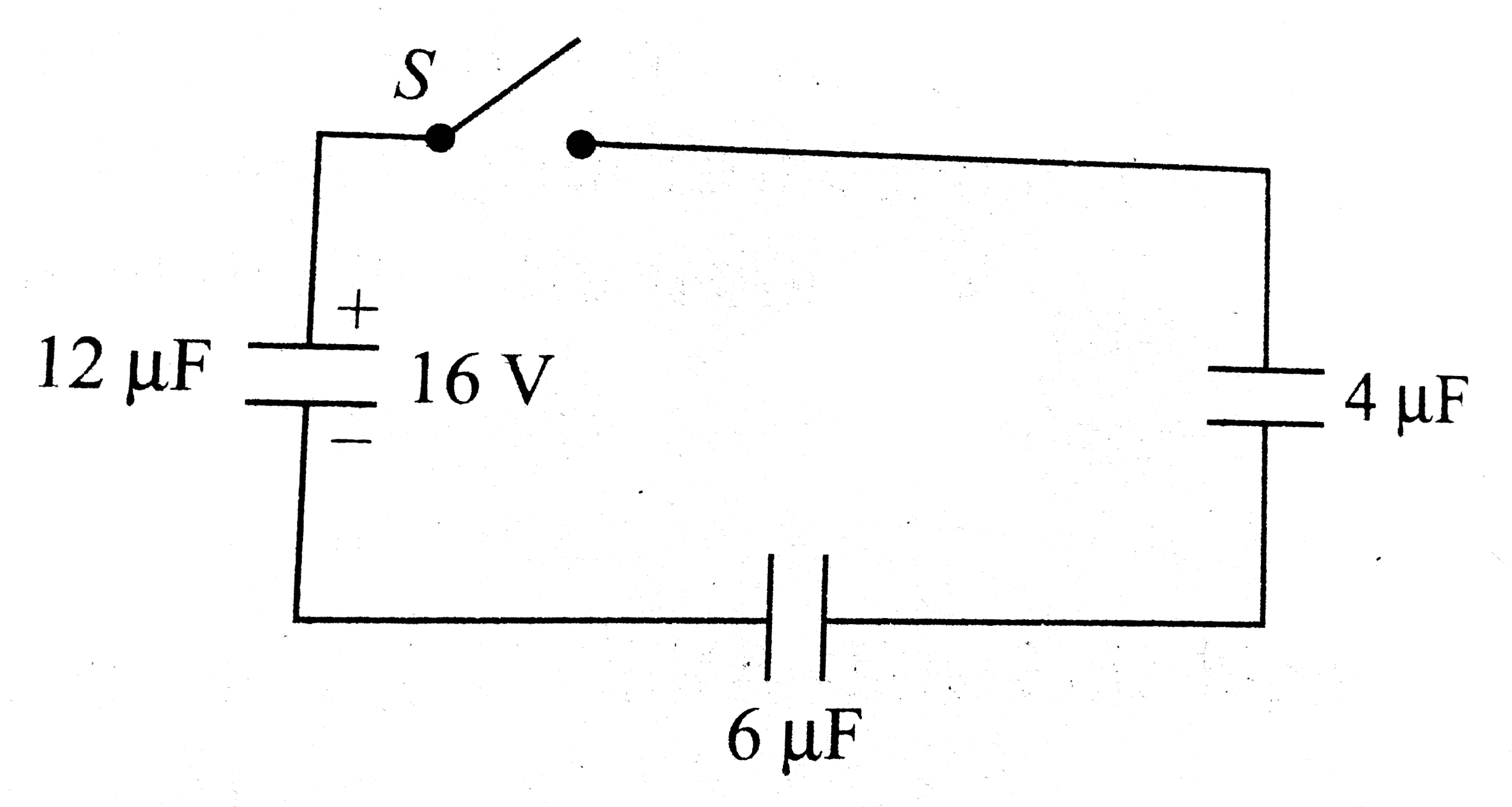
the final charge on the 6μF capacitorA12μCB24μCC32μCD48μc - Question 1 - Select One
In the adjoning figure, the potential difference across the 4.5μF capacitor is
 A4 VB6 VC8 VD4.5 V
 - Question 1 - Select One
In the circuit shown in the figure, the potential difference across the 4.5μF capacitor is
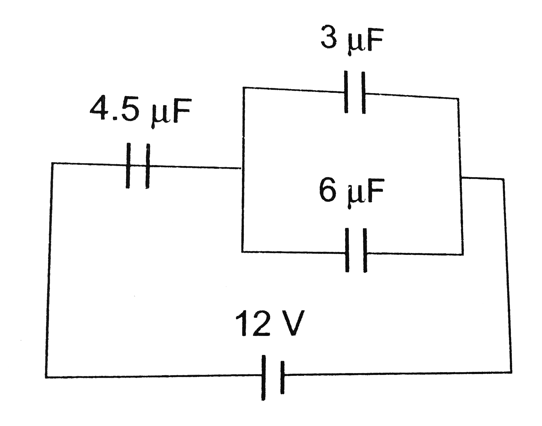 A83voltsB4 voltsC6 voltsD8 volts
 - Question 1 - Select One
The two capacitors in the circuit shown in figure are initially uncharged and then connected as shown and switch is closed. What is the potential difference across 3μF capacitor?
 A30VB10VC25VDNone of these


