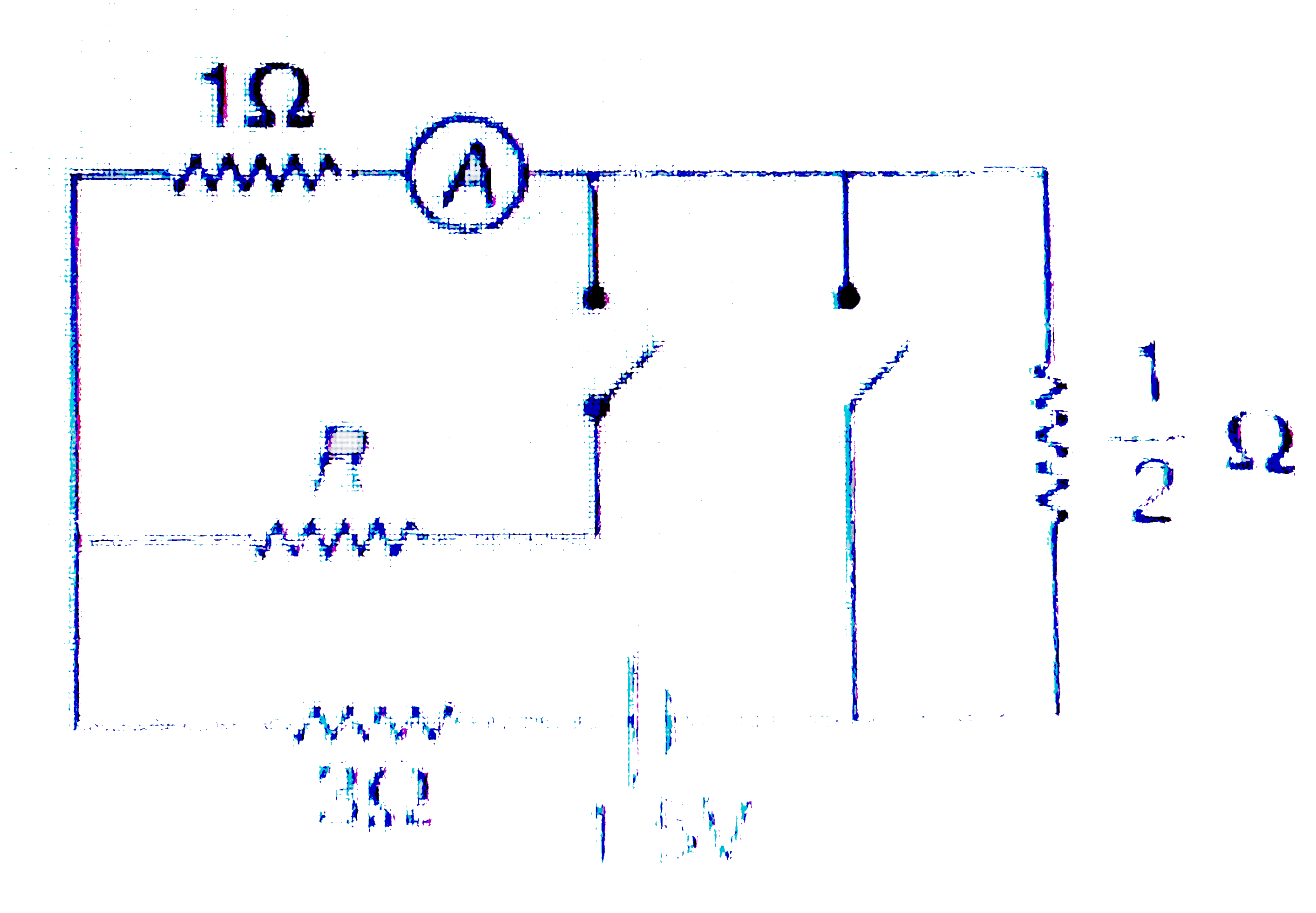
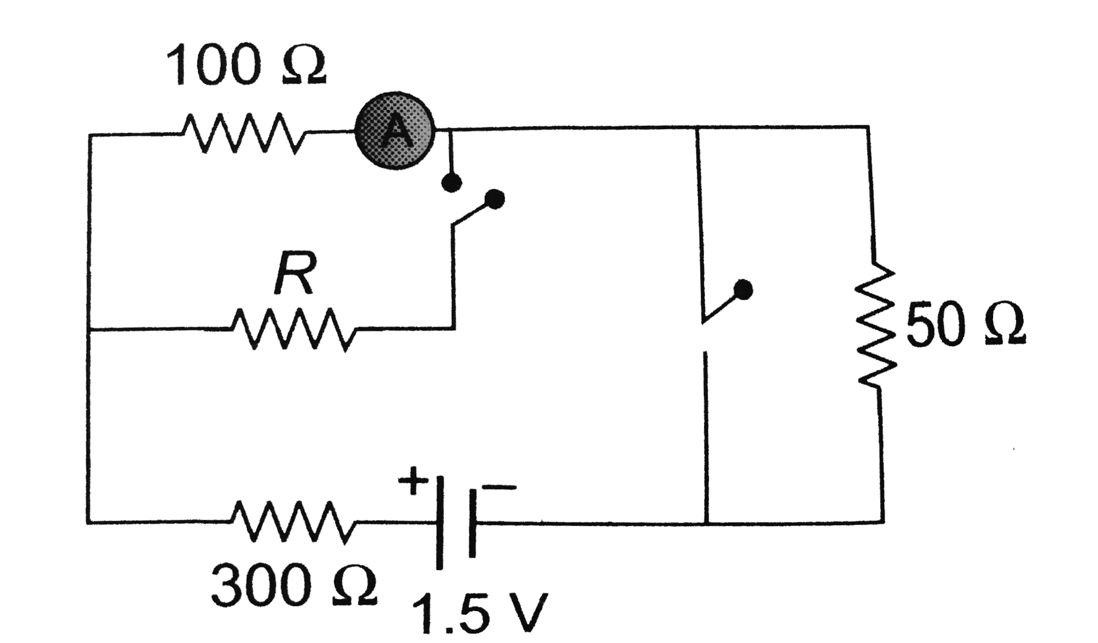
In the circuit shown in figure the reading of ammeter is the same with both switches open as with both closed. Then find the resistance R. (ammeter is ideal).
Video Solution
Text Solution
Step I: Discuss the circuit when both switches are open:
According to loop rule: 1.5−300I−100I−50I=0
∴I=1.5450=154500
=1300A
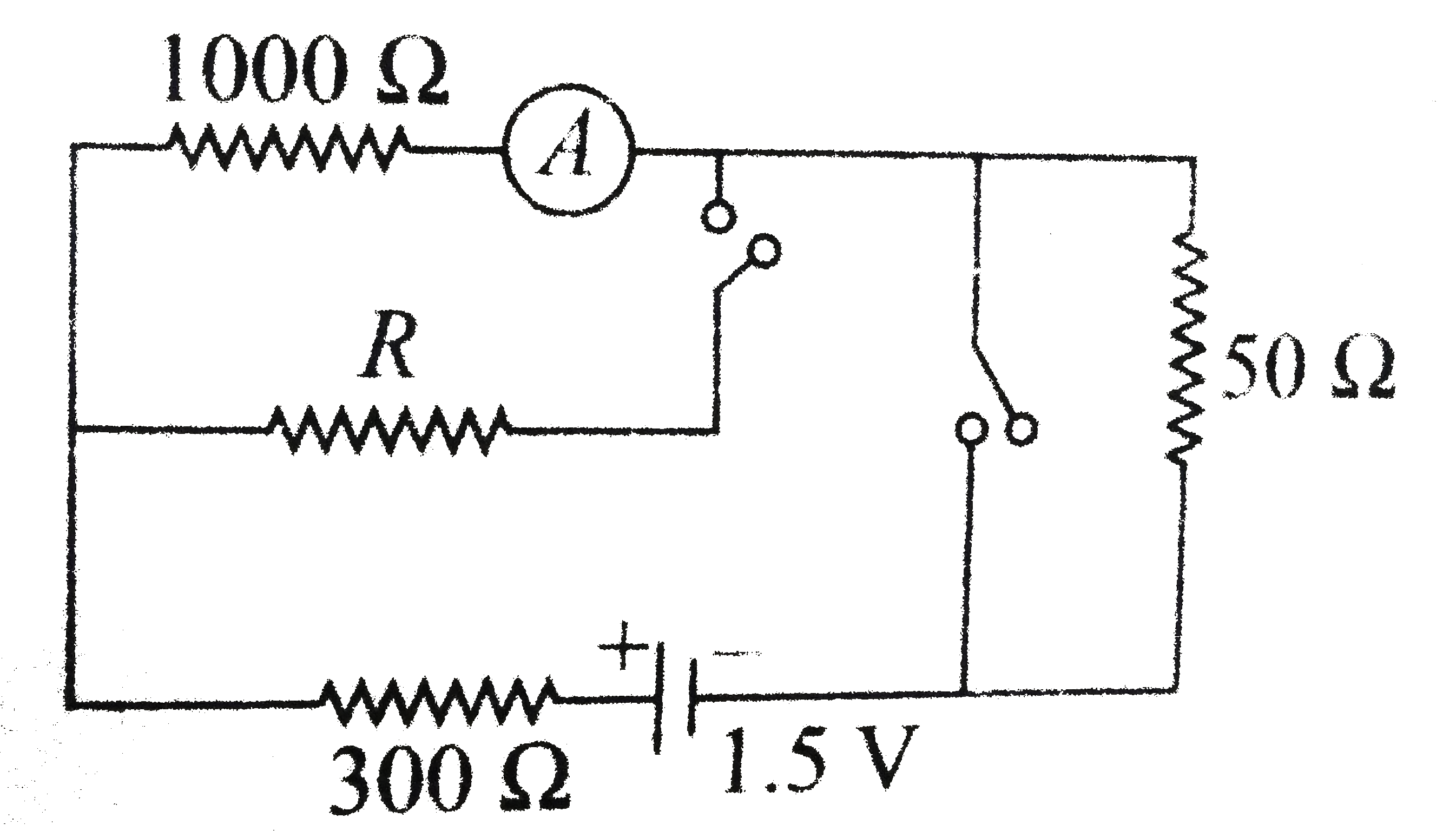
Step II: Discuss the circuit
after closing the switch.
In loop ABCDEA,
−IR+1.5−300I1=0
or 300I1+IR=1.5.....(i)
In loop BCGFB,
−100I+(I1−I)R=0
or (I1−I)R=100I
or I1R=(100+R)I
∴I1=(100+R)IR........(ii)
From eqs. (i) and (ii),
300(100+R)IR+IR=1.5
or 300100+RR1300+R300=1.5
∴R=6000Ω.
|
Updated on:21/07/2023
Related Playlists
- BOOK - CENGAGE PHYSICSCHAPTER - MISCELLANEOUS VOLUME 3EXERCISE - True and False3videos
MISCELLANEOUS VOLUME 3
- BOOK - CENGAGE PHYSICSCHAPTER - MISCELLANEOUS VOLUME 3EXERCISE - Assertion and Reason8videos
MISCELLANEOUS VOLUME 3
- BOOK - CENGAGE PHYSICSCHAPTER - MECHANICAL PROPERTIES OF SOLIDSEXERCISE - Question Bank4videos
MECHANICAL PROPERTIES OF SOLIDS
- BOOK - CENGAGE PHYSICSCHAPTER - MISCELLANEOUS VOLUME 5EXERCISE - Integer12videos
MISCELLANEOUS VOLUME 5
Similar Practice Problems
- Question 1 - Select One
In the circuit shown in figure, reading of ammeter will
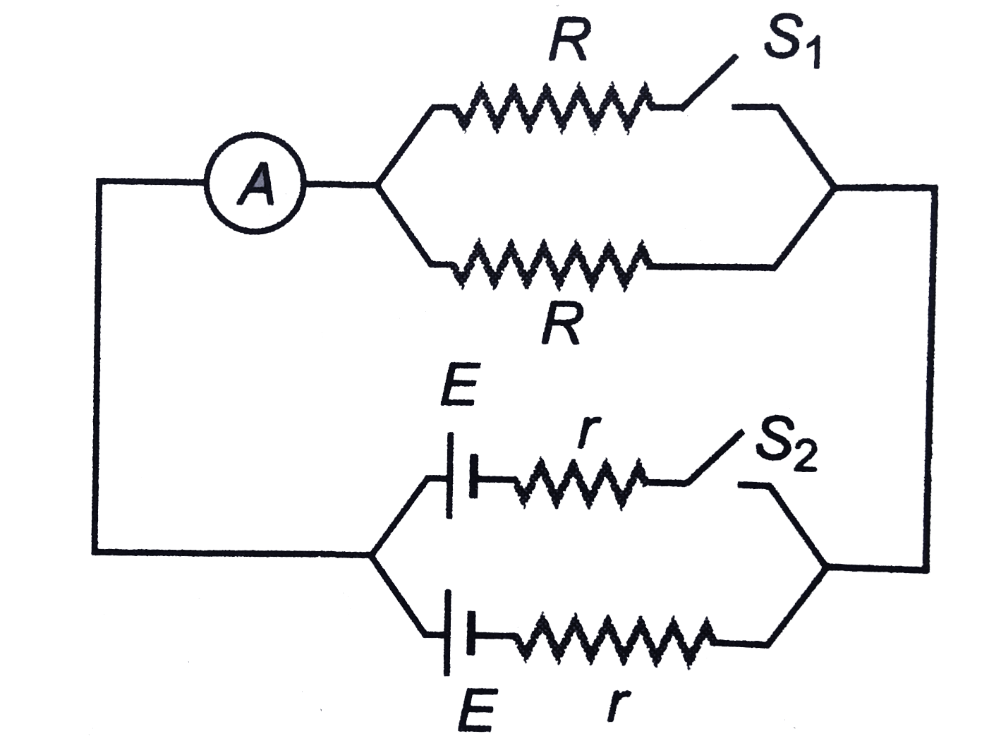 Ashows no deflection if S1 is closedBdecrease if S2 is closedCincrease if S2 is closedDdecrease if S2 is closed
 - Question 1 - Select One
In the circuit shown, the reading of ammeter is:
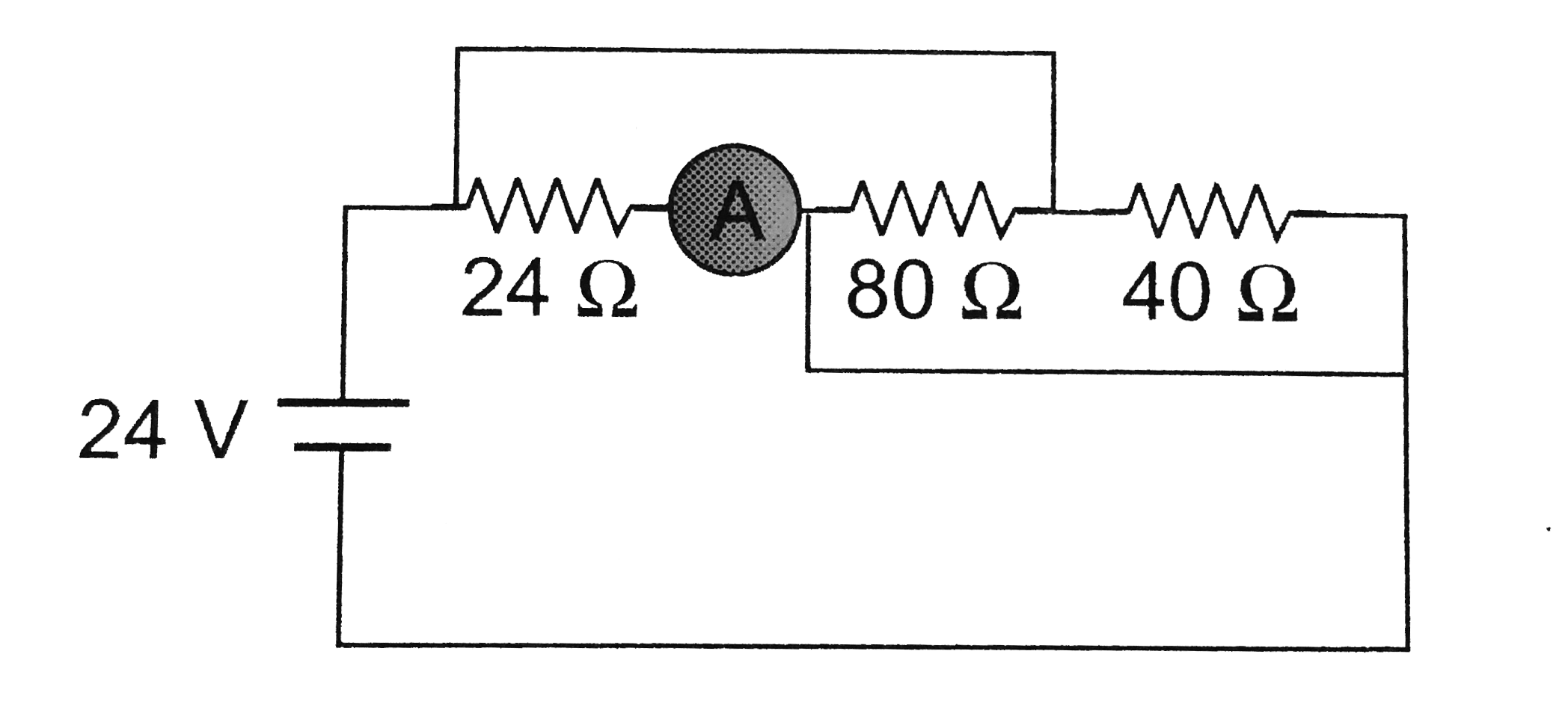 A0.2AB0.6AC2AD1A
 - Question 1 - Select One
In the circuit shown P≠R the reading of galvonometer is same switch S open or closed. Then
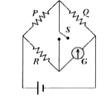 AIR=IGBIP=IGCIQ=IGDIQ=IS
 - Question 1 - Select One
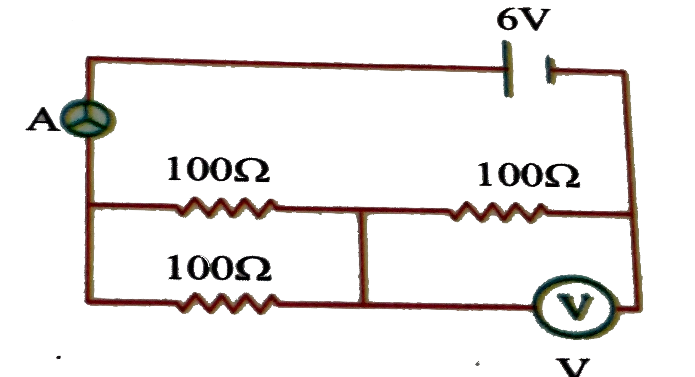
In the circuit shown, the reading of the voltmeter and the ammeter areA4V.0.2AB2V,0.4AC3V,0.6AD4V,0.04A - Question 1 - Select One
In the circuit P≠R, the reading of the galvanometer is same with switch S open or closed. Then
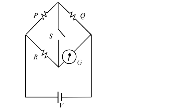 AIR=lGBIp=lGClQ=lGDIR=IQ
 - Question 1 - Select One
The reading of ammeter in the circuit shown will be
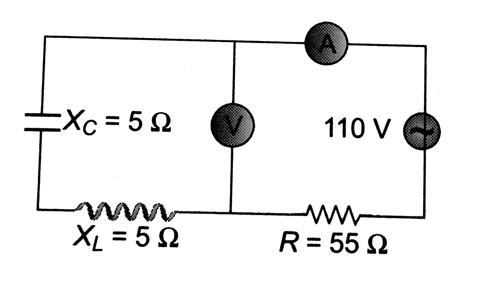 A2AB2.4ACzeroD1.7A
 - Question 1 - Select One
In the circuit shown, the reading of the ammeter if diode is not ideal, will be
 A0B15mAC>15mAD<15mA
 - Question 1 - Select One
In the circuit shown in figure, what will be the readings of voltmeter and ammeter?
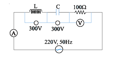 A800 V, 2 AB220 V, 2.2 AC300 V, 2 AD100 V, 2 A


