In the circuit shown in figure (1), the V0,I1,ID1, and ID3 are respectively.
(A) 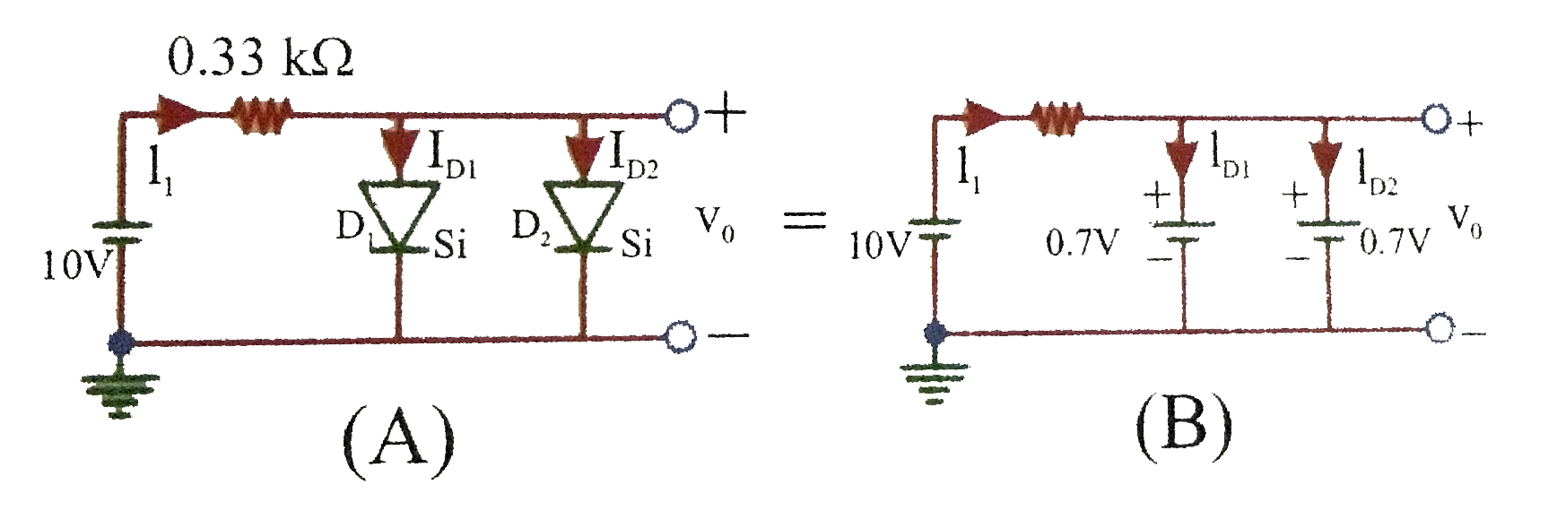
A
0.5V,25mA,15mA
B
0.7V,28mA,14.09mA
C
0.4V,15mA,20mA
D
0.3V,15.06mA,20.18mA
Video Solution
Text Solution
The correct Answer is:B
Since applied voltage is greater than 0.7V and direction of current is same as direction of arrow head, both the diodes are in ''on'' state (see above figure(2)). Now V0 is parallel to D1 and D2.
Hence V0=0.7V
Current I1=VRR=E−VDR=10V−0.7V0.33kΩ=28.18mA
Both the silecon diodes have similar characteristics.
Hence ID1=ID2=I12=14.09mA.
|
Updated on:21/07/2023
Related Playlists
- BOOK - NARAYNACHAPTER - SEMI CONDUCTOR DEVICESEXERCISE - NCERT (Comprehension)13videos
SEMI CONDUCTOR DEVICES
- BOOK - NARAYNACHAPTER - SEMI CONDUCTOR DEVICESEXERCISE - Level-I (H.W)26videos
SEMI CONDUCTOR DEVICES
- BOOK - NARAYNACHAPTER - SEMI CONDUCTOR DEVICESEXERCISE - Level-II (C.W)33videos
SEMI CONDUCTOR DEVICES
- BOOK - NARAYNACHAPTER - RAY OPTICS AND OPTICAL INSTRAUMENTS EXERCISE - EXERCISE- 4 One or more than one correct answer type13videos
RAY OPTICS AND OPTICAL INSTRAUMENTS
- BOOK - NARAYNACHAPTER - SEMICONDUCTOR ELECTRONICSEXERCISE - ADDITIONAL EXERCISE (ASSERTION AND REASON TYPE QUESTIONS :)19videos
SEMICONDUCTOR ELECTRONICS
Knowledge Check
- Question 1 - Select One
In the circuit shown in figure I1,I2 and ID2 are respectively-
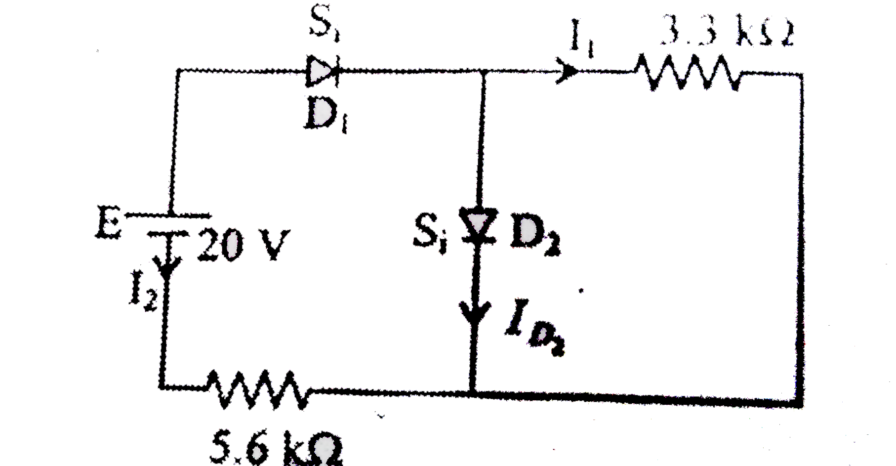 A0.212MA,3.32mA,3.108mAB2.12mA,3.32mA,3.108mAC0.212mA,0.332mA,3.108mADNone of these
 - Question 1 - Select One
In the circuit shown, the currents i1 and i2 are
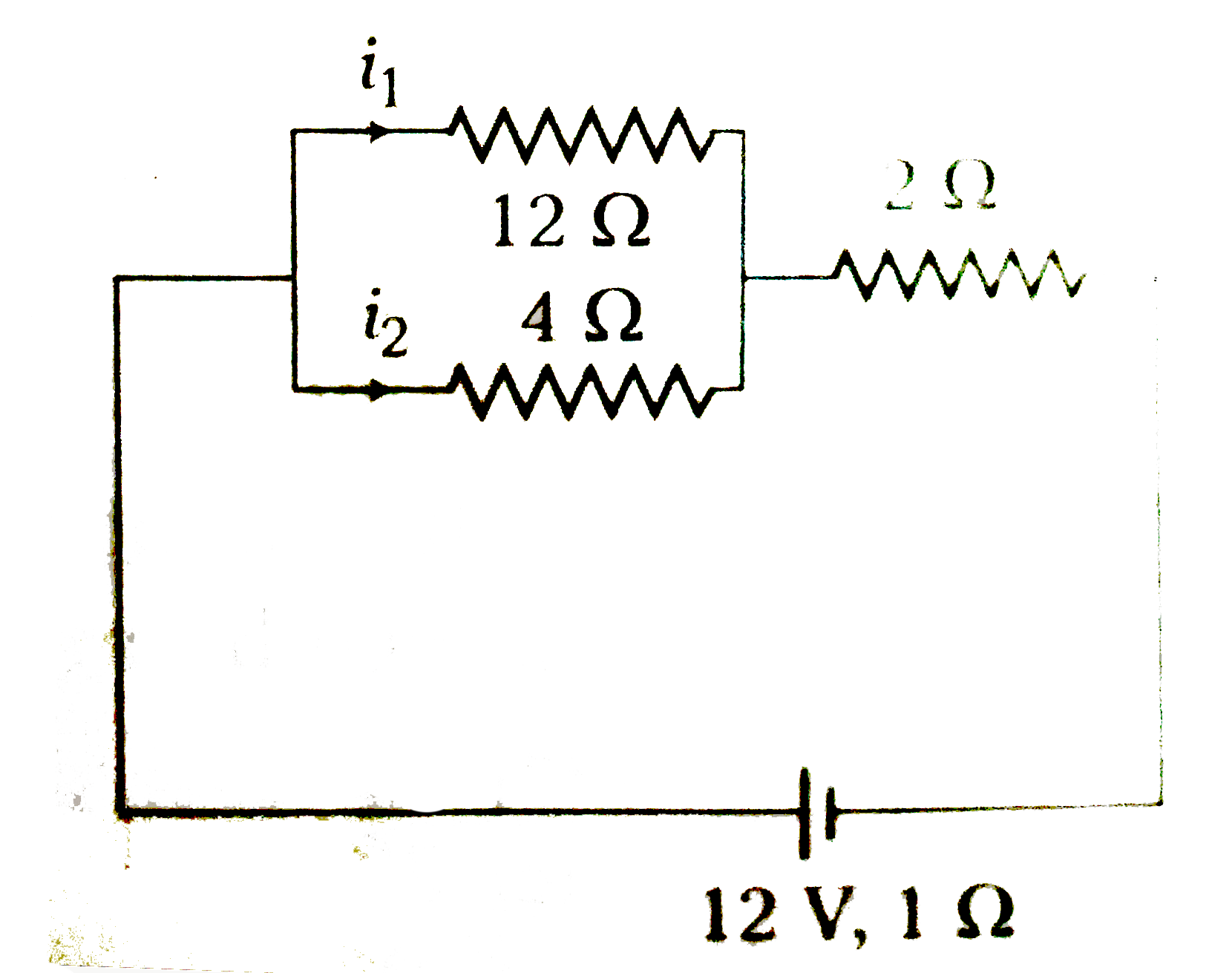 Ai1=1.5A,i2=0.5ABi1=0.5A,i2=1.5ACi1=1A.i2=3ADi1=3A,i2=1A
 - Question 1 - Select One
In the circuit shown, the value of currents I1,I2andI3 are
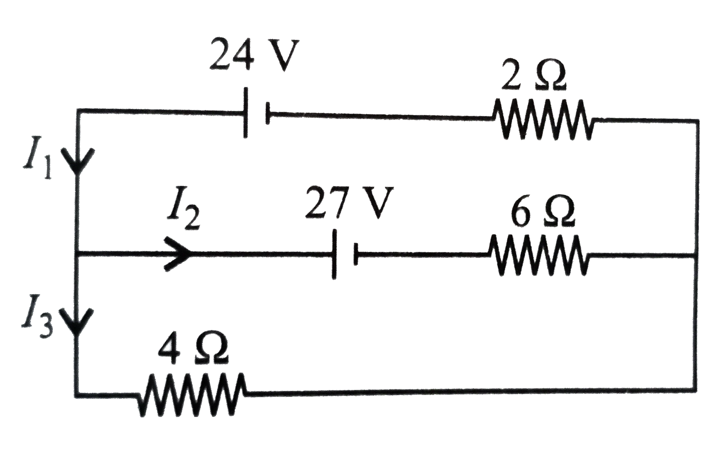 A3A,−3A2A,92AB92A,−32AC5A,4A,−3AD7A,54A,92A
 - Question 1 - Select One
In the circuit as shown in figure, the ratio of current i1/i2 is
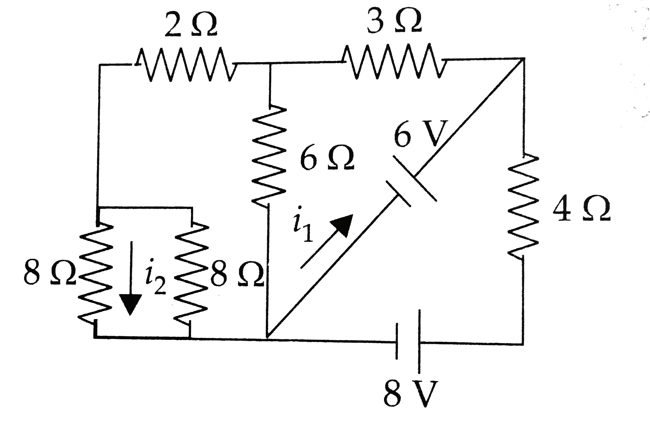 A4/3B1/2C2Dnone of these
 - Question 1 - Select One
In the circuit shown in the figure
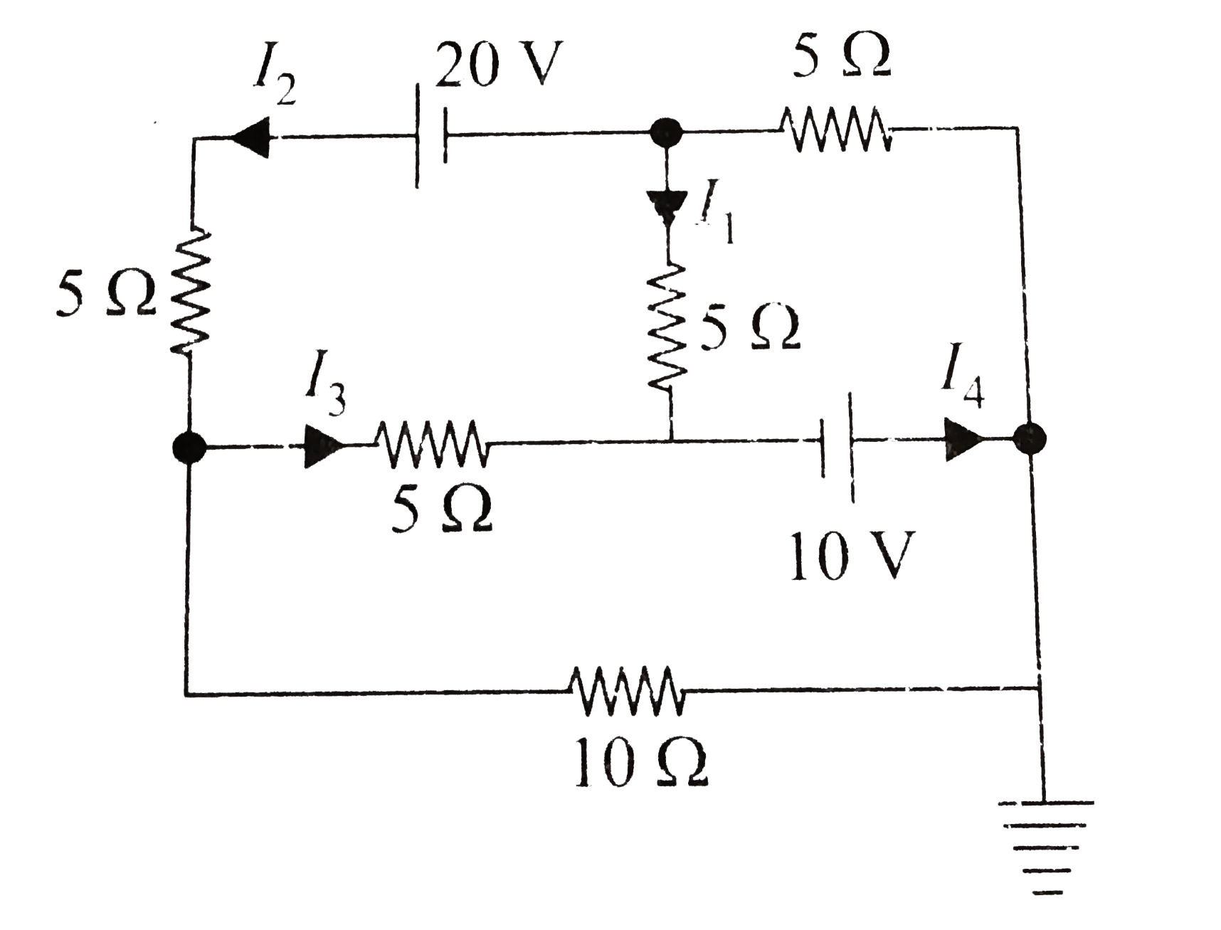 .
.
The value of current I1 isA2ABzeroC2.5 ADnone of these - Question 1 - Select One
In the circuit shown, the switch is closed at t=0, the currents I1,I2 and I3 are
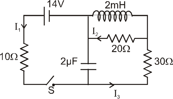 A1.4A,0,0B1.4 A,0.70 A,0.70 AC0,0,0D1.2A,0.6A,0.6A
Similar Questions
In the circuit shown in the figure. find I1andI2.
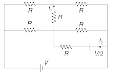 View Solution
In the circuit shown in fig., the value of I1+I2 is
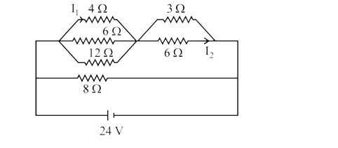 View Solution
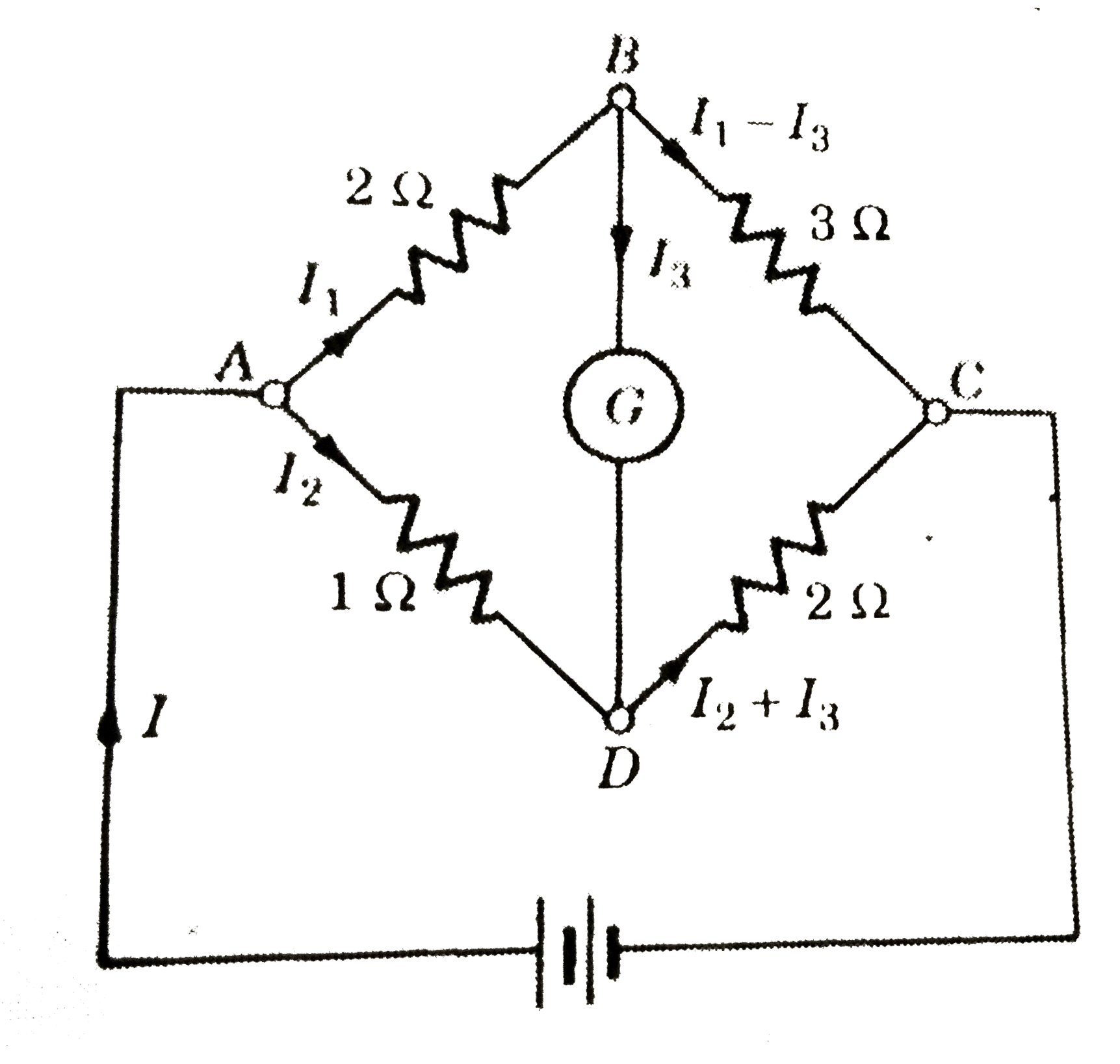
In the circuit shown in figure. Find the currents I,I1,I2andI3 given that emf of th battery=2V, internal resistance of the battery =2Ω and resistance of the galvanomter =4Ω.View SolutionIn the circuit shown in figure ,find the ratio of currents i1/i2.
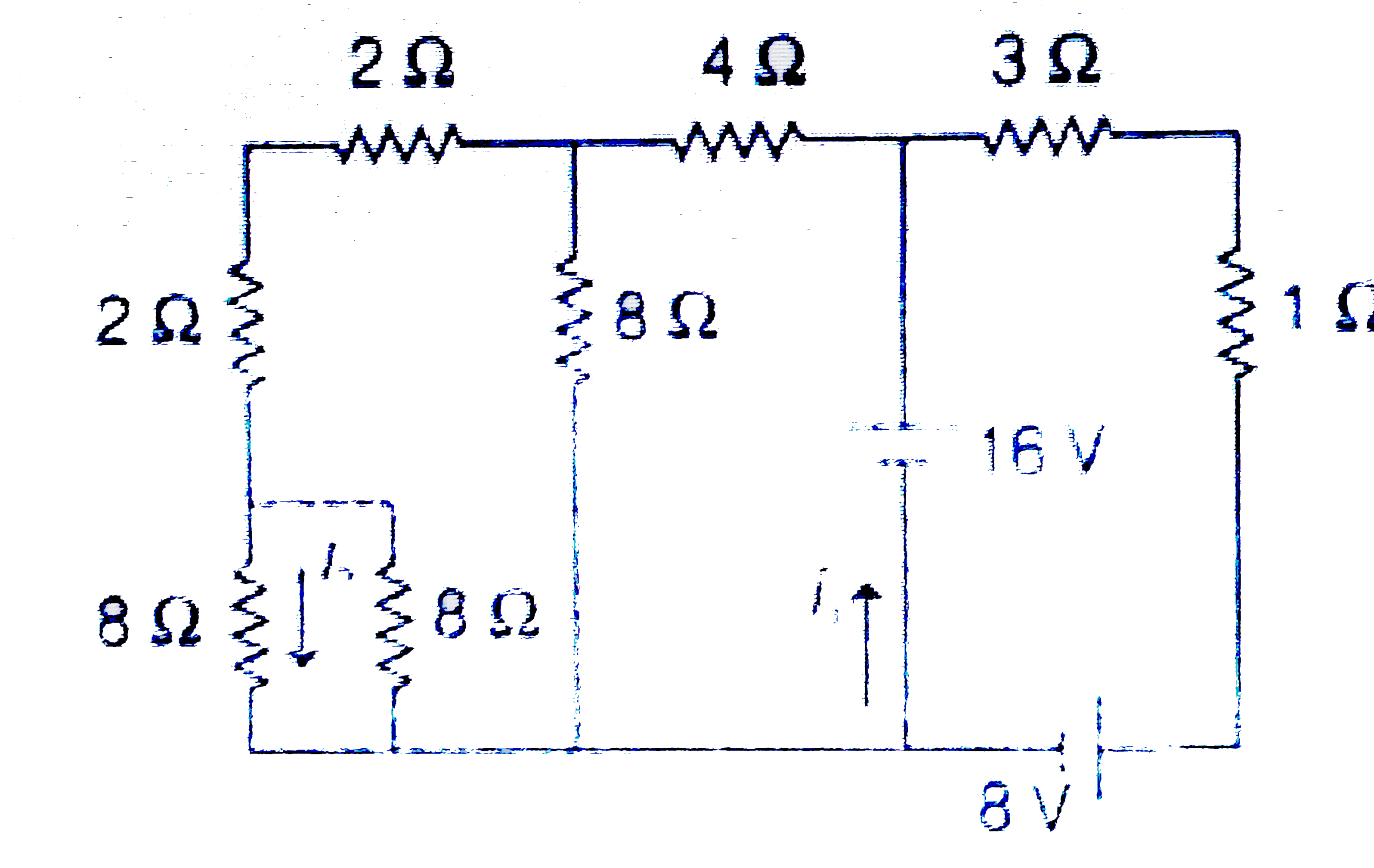 View Solution

