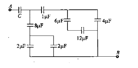
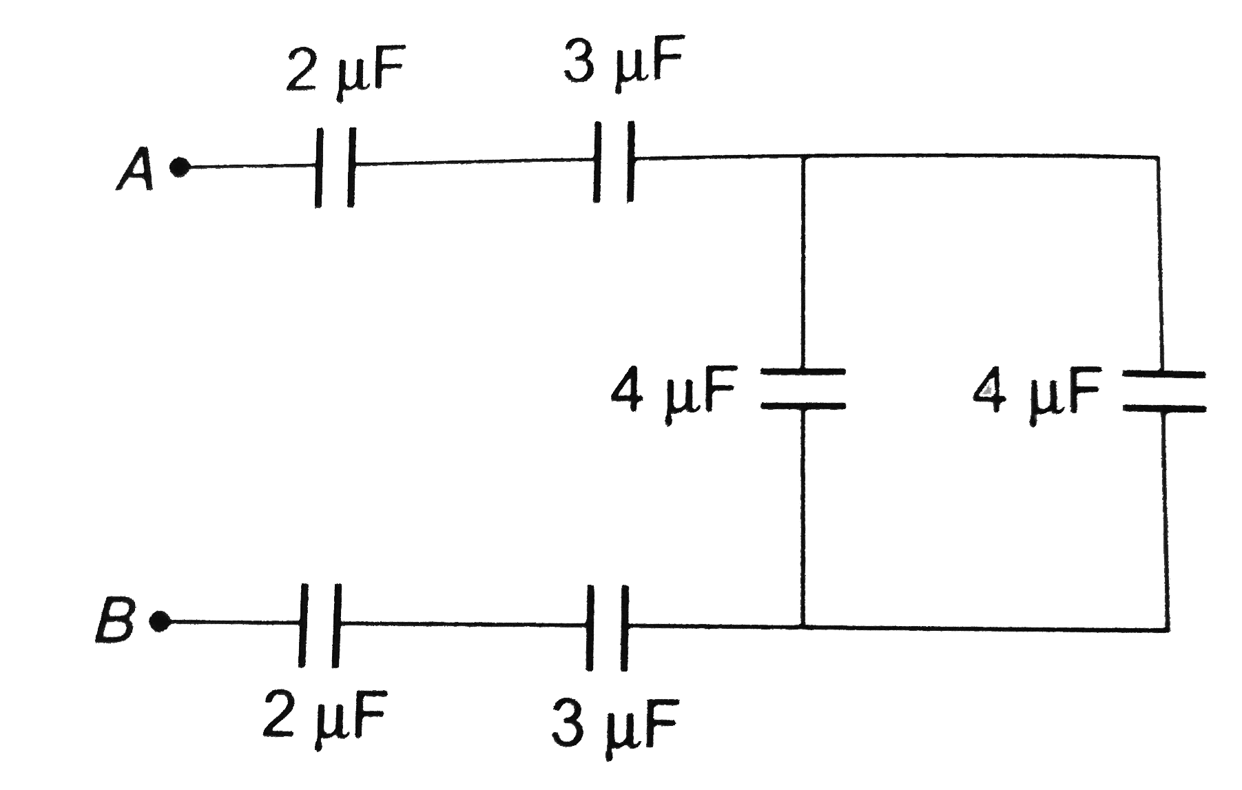
In the circuit as shown in the figure the effective capacitance between A and B is
A
3μF
B
2μF
C
4μF
D
8μF
Video Solution
Text Solution
The correct Answer is:C
|
Answer
Step by step video, text & image solution for In the circuit as shown in the figure the effective capacitance between A and B is by Physics experts to help you in doubts & scoring excellent marks in Class 12 exams.
Updated on:21/07/2023
Related Playlists
Knowledge Check
- Question 1 - Select One
In the circuit as shown in the figure the effective capacitance between A and B is
 A3μFB2μFC4μFD8μF
 - Question 1 - Select One
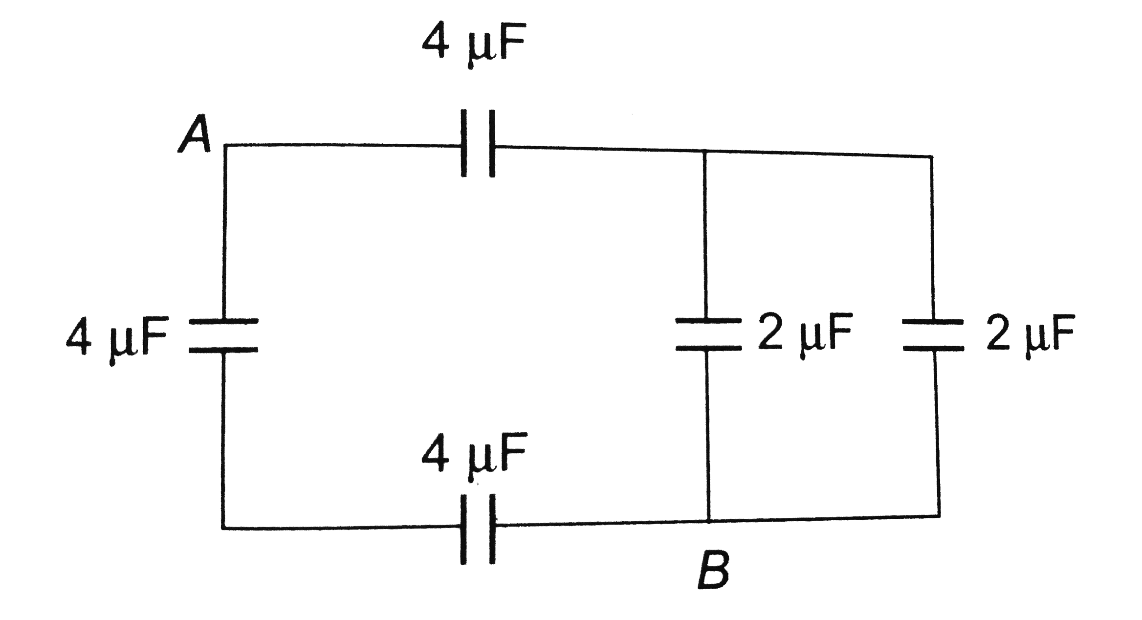
Six capacitors each of capacitance of 2μF are connected as shown in the figure. The effective capacitance between A and B is:
 A12μFB8/3μFC3μFD6μF
 - Question 1 - Select One
Eight capacitors , each of capacitance 2μF are conneted as shown in the figure . The effective capacitance between point A and B is
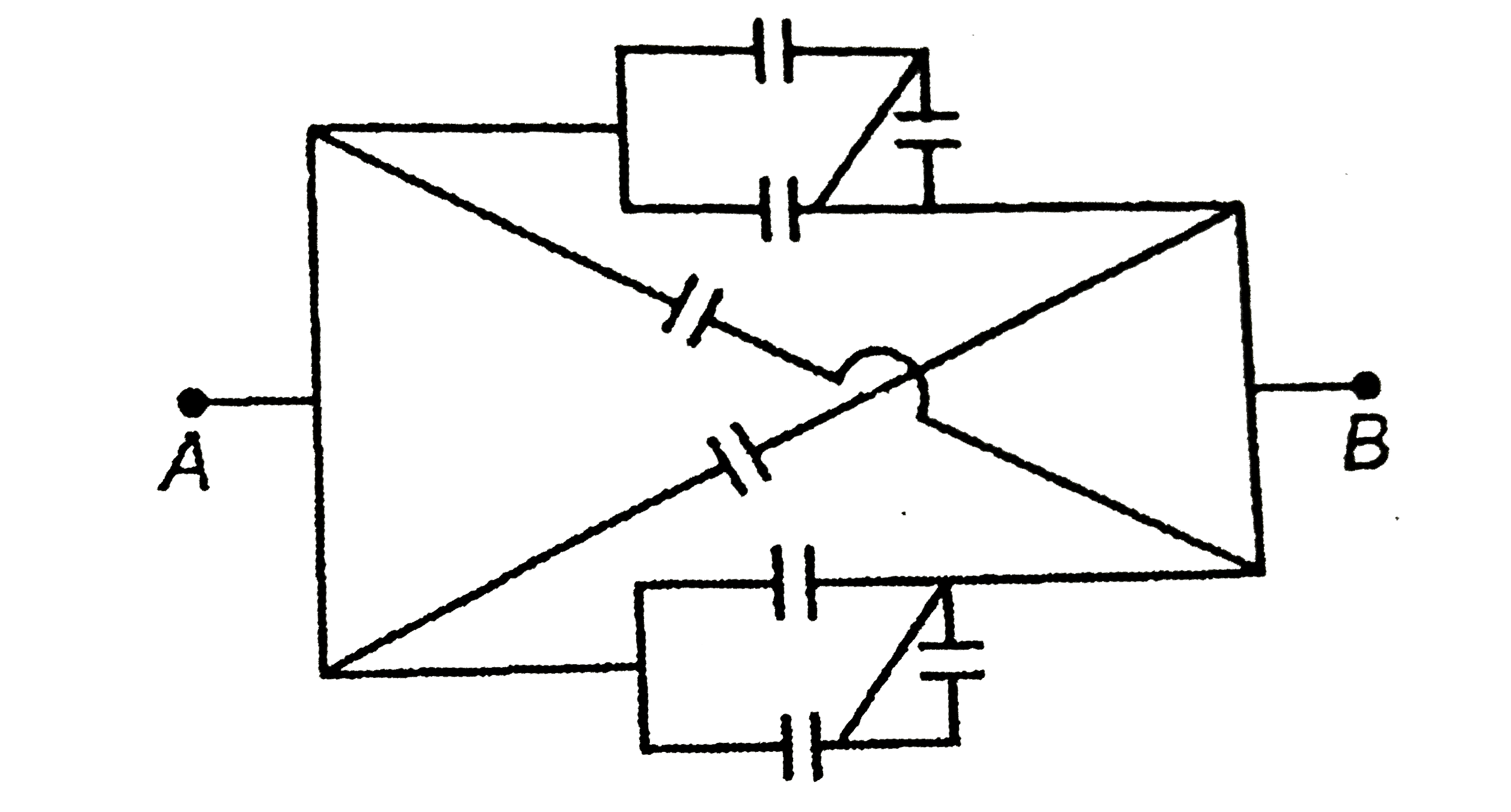 A10μFB12μFC8μFDZero
 - Question 1 - Select One
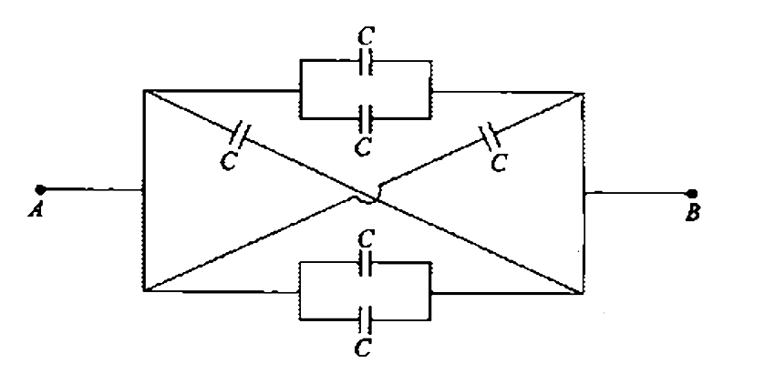
Four capacitors are connected in a circuit as shown in the figure. The effective capacitance in μF between points A and B will be
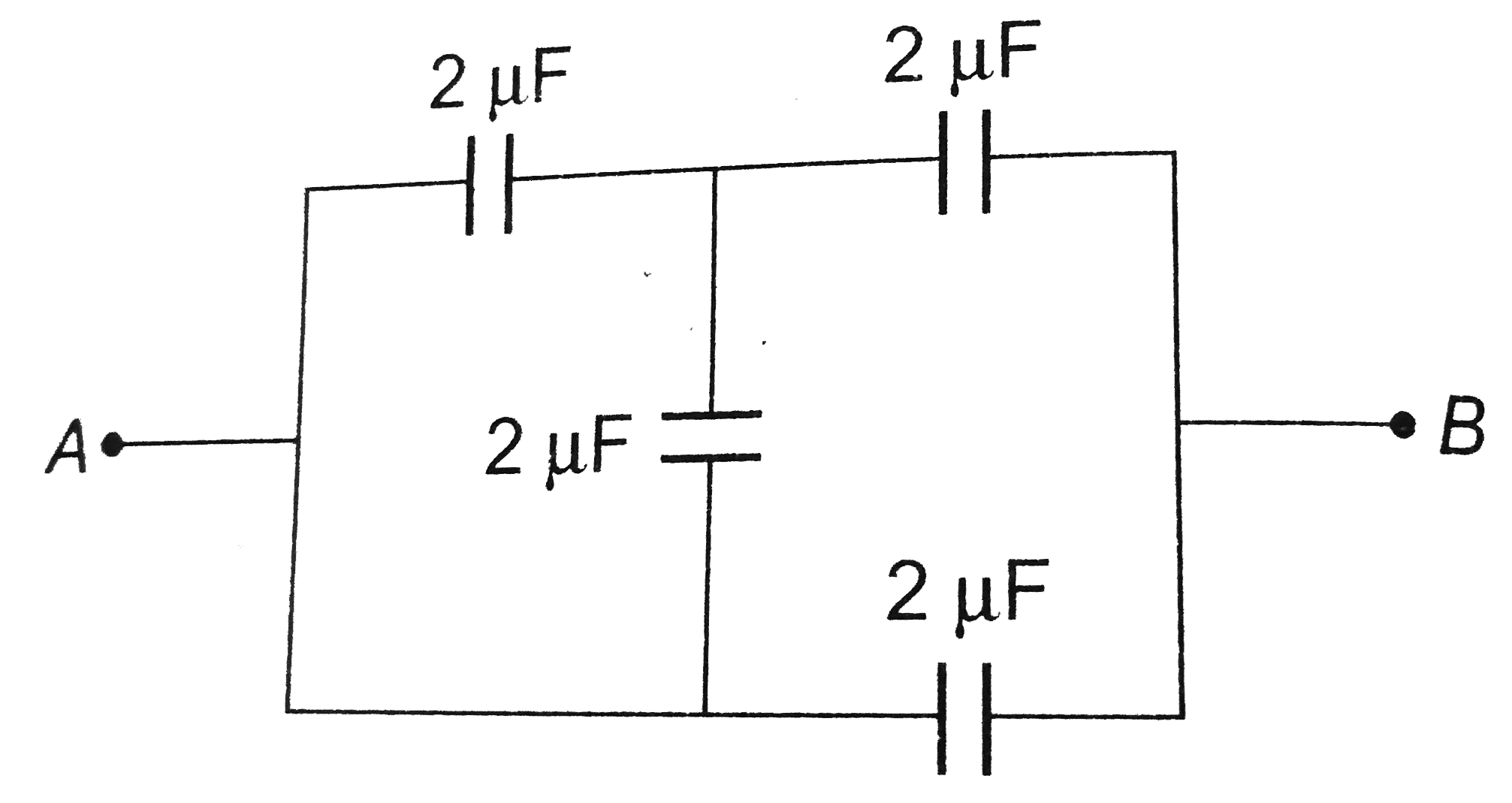 A289B4C5D18
 - Question 1 - Select One
Consider an infinite matrix of capacitors as shown in the figure.
The effective capacitance between point A and B will be
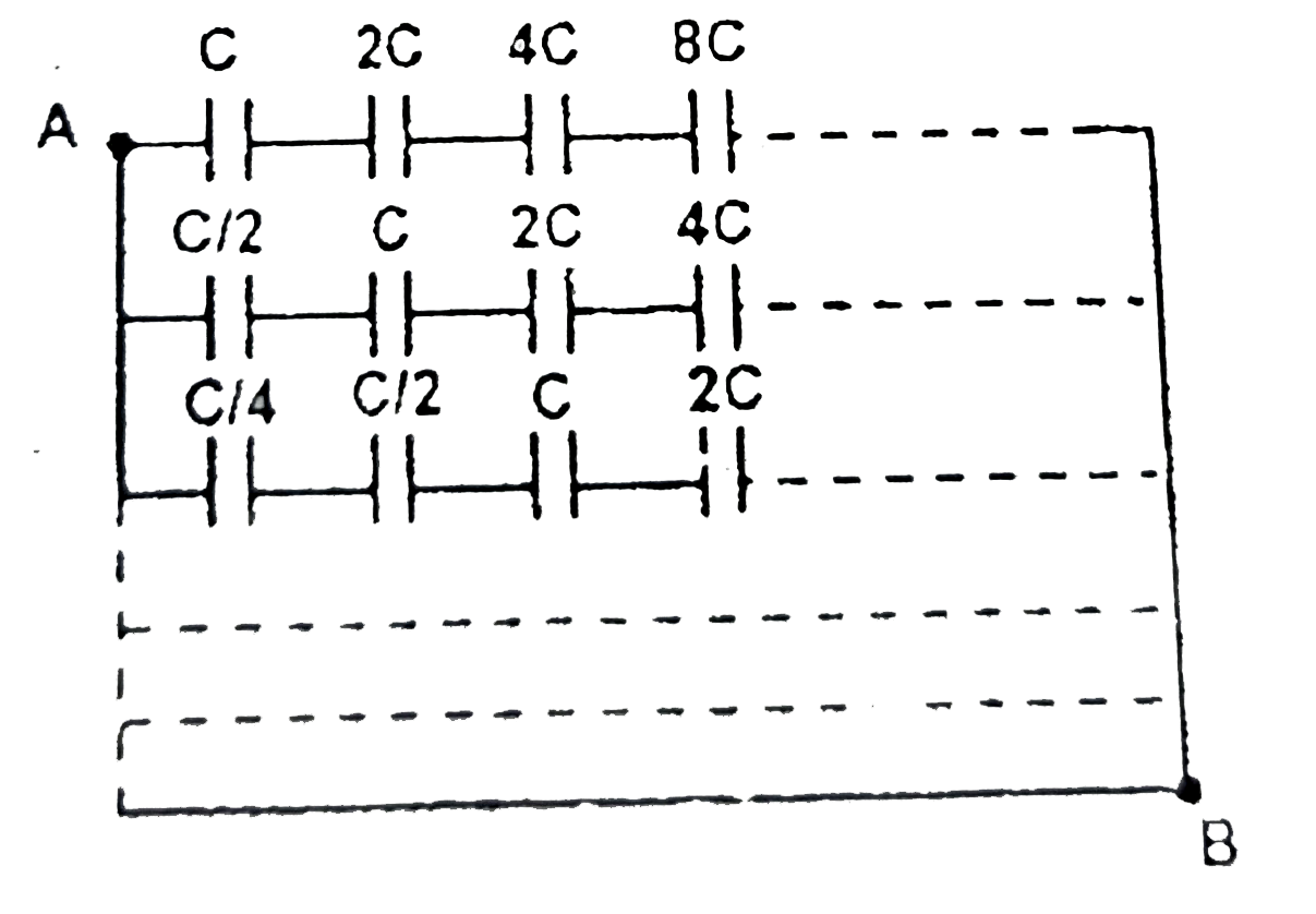 ACB2CC∞Dcan't be determined.
 - Question 1 - Select One
An infinite number of identical capacitors each of capacitance 1mF are connected as shown in the figure. Then the equivalent capacitance between A and B is.
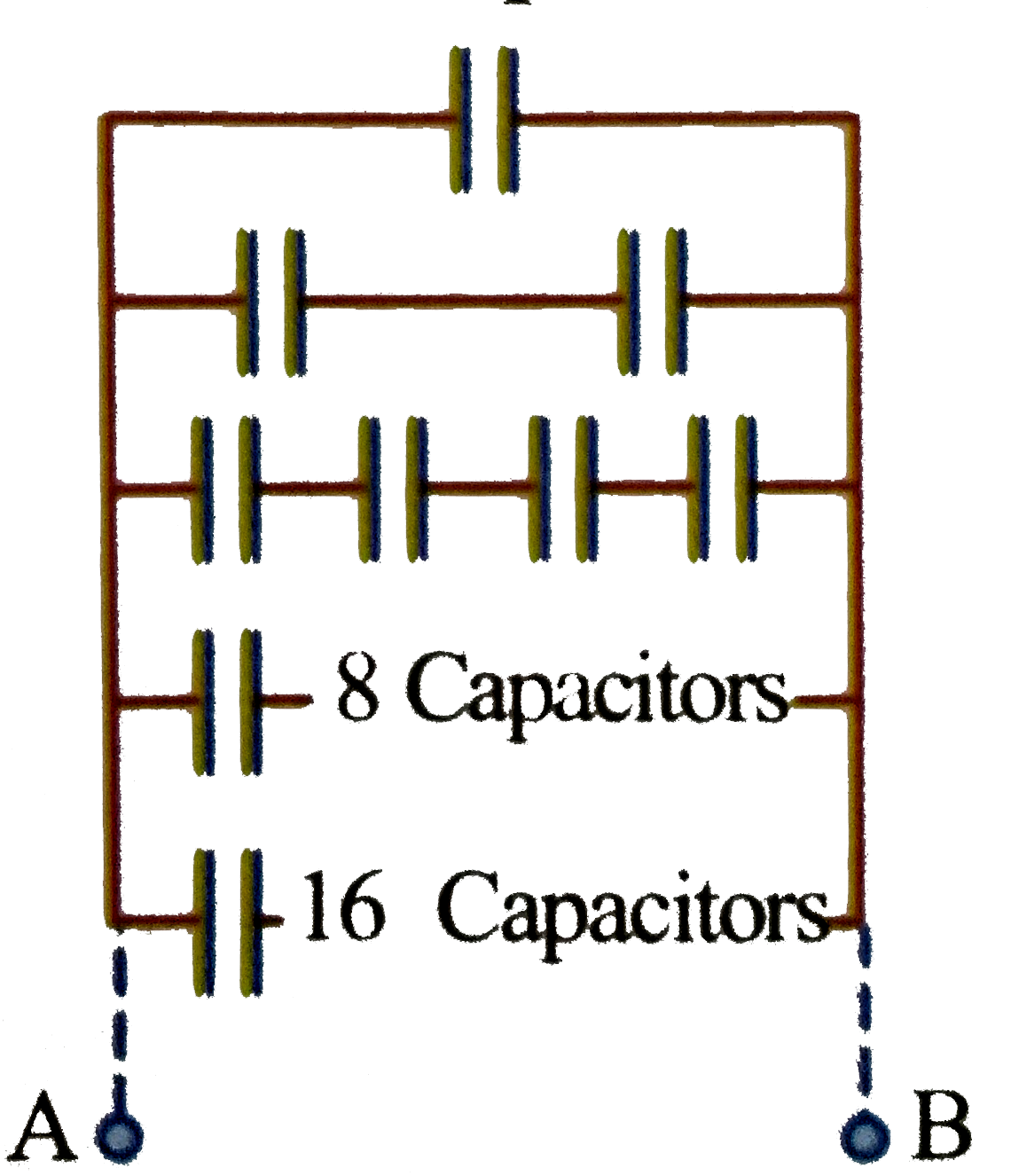 .A1mFB2mFC1/2mFD0.75mF
 - Question 1 - Select One
The effective capacitance between A and B in the figure given is
 A4324μFB2443μFC4312μFD1243μF
 - Question 1 - Select One or More
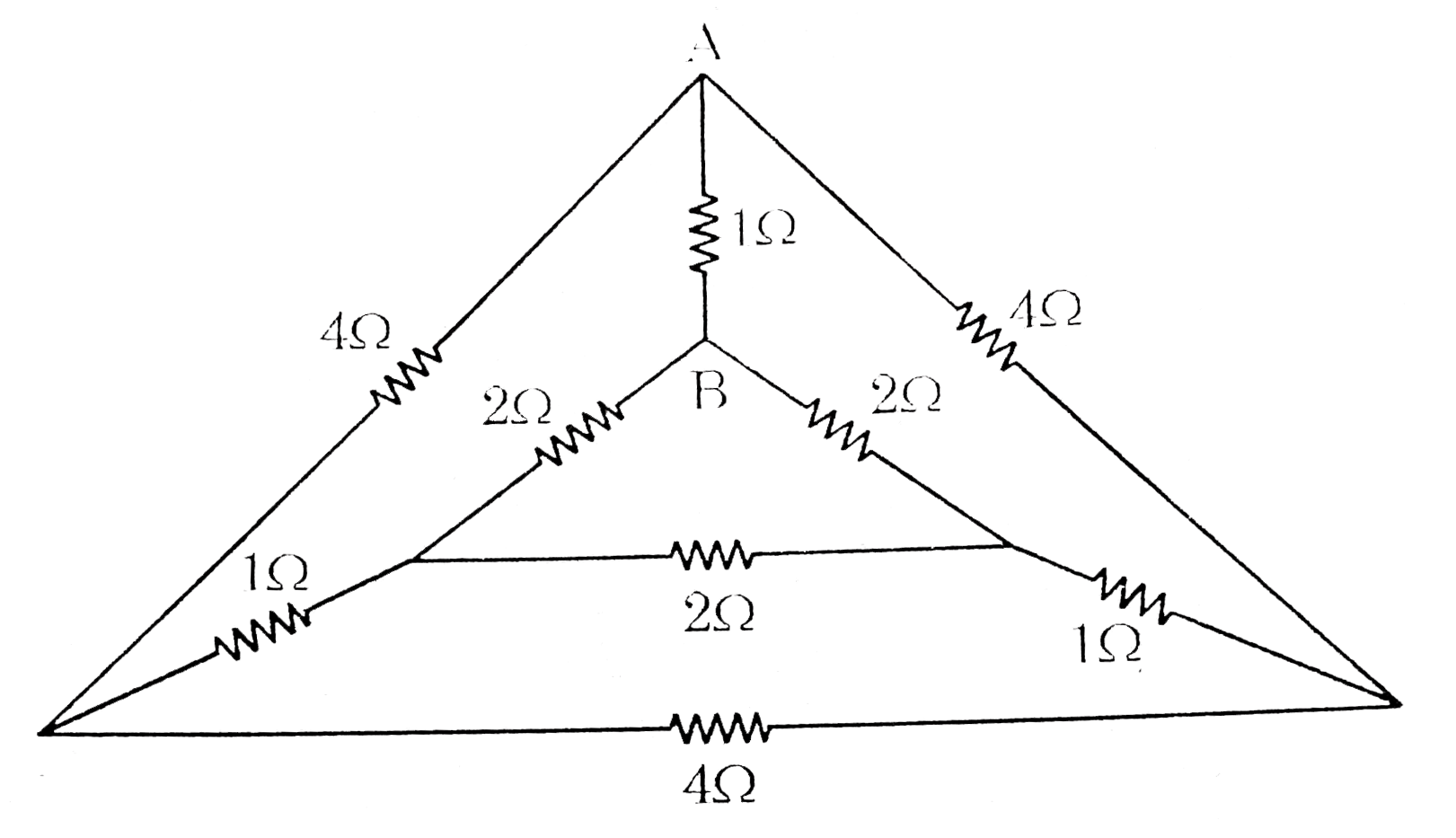
Consider the circuit as shown in figure. The equivalent resistance between A and B is
 A97ΩB19ΩC79ΩDNone


