Solved Examples from CENGAGE PHYSICS (ENGLISH) INDUCTANCE for Class 12
| Class 12 | PHYSICS |
| Chapter | INDUCTANCE |
| CENGAGE PHYSICS (ENGLISH) | Solved Examples |
| Medium | English |
| Academic Year | 2023-2024 |
Question 5
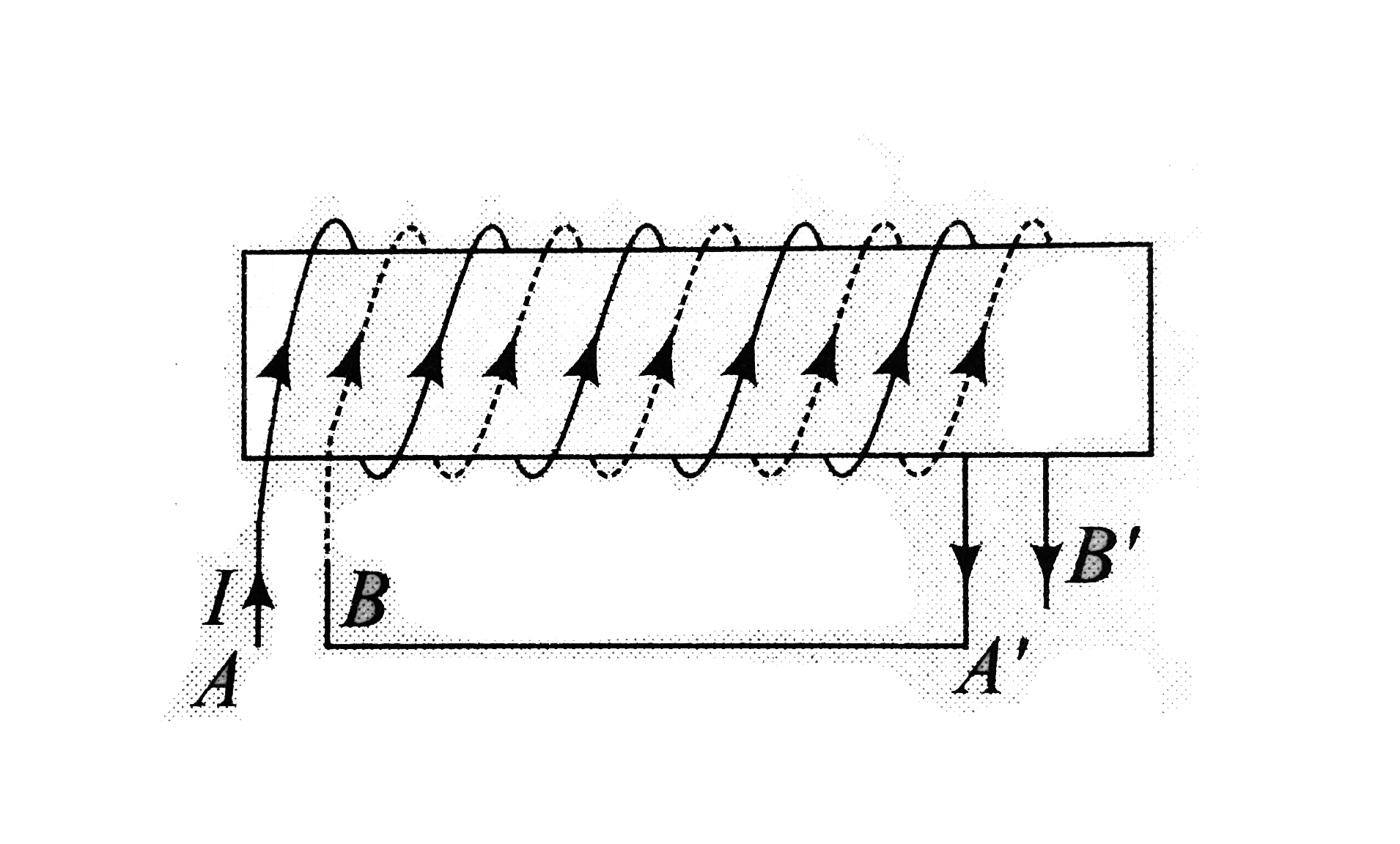
In Fig. coil 1 and coil 2 are wound on a long cylindrical insulator. The ends A' and B are joined together and current I is passed. Self-inductance of the two coils are L1 and L2, and their mutual inductance is M.
a. Show that this combination can be replaced by a single coil of equivalent inductange given by
Leq=L1+L2+2M.
b. How could the coils be reconnected by yieldings an equivalent inductance of Leq=L1+L2−2M.
 View Solution
Question 13
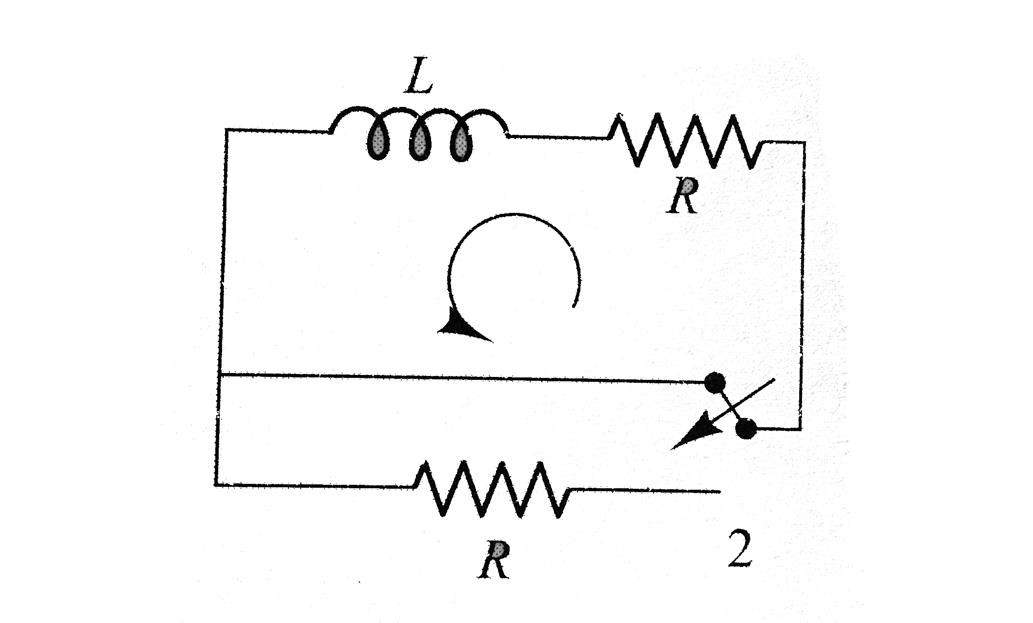
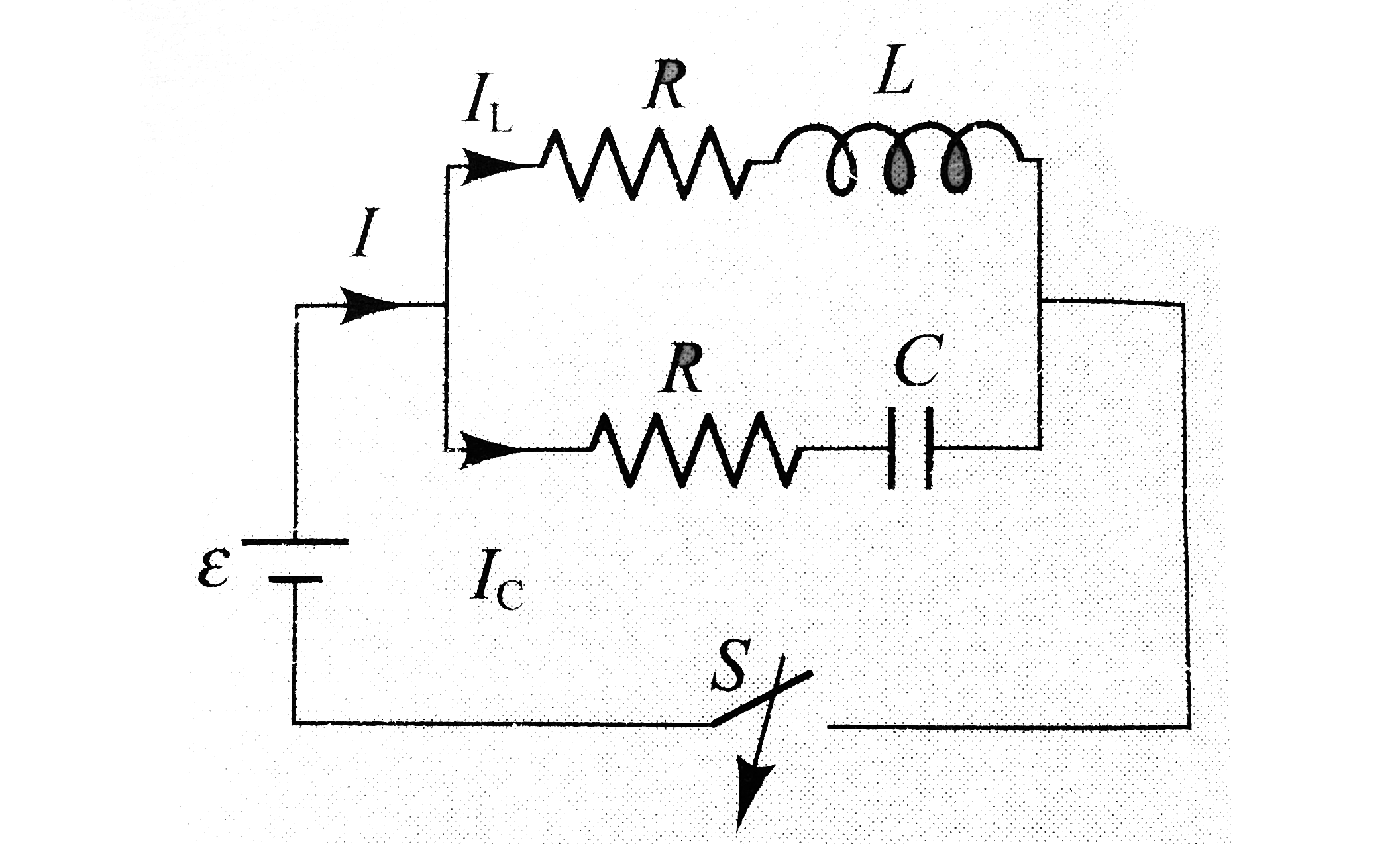
Consider the RL circuit in Fig. When the switch is closed in position 1 and opens in position 2, electrical work must be performed on the inductor and on the resistor. The energy stored in the inductor is for the resistor energy appears as heat.
a. What is the ratio of PL/PR of the rate at which energy is stored in the inductor to the rate at which energy is dissipated in the resistor?
b. Express the ratio PL/PR as a function of time.
c. If the time constant of circuit is t, what is the time at which PL=PR? View SolutionQuestion 16
Initially the 900μF capacitor is charged to 100V and the 100μFcapacitor is uncharged in Fig. Then switch S2 is closed for time t1, after which it is opened and at the same instant switch S1 is closed for time t2 and then opened. It is now found that 100μF capacitor is charged to 300μF capacitor is charged to 300V. Find the minimum possible value of the time interval t1 and t2.
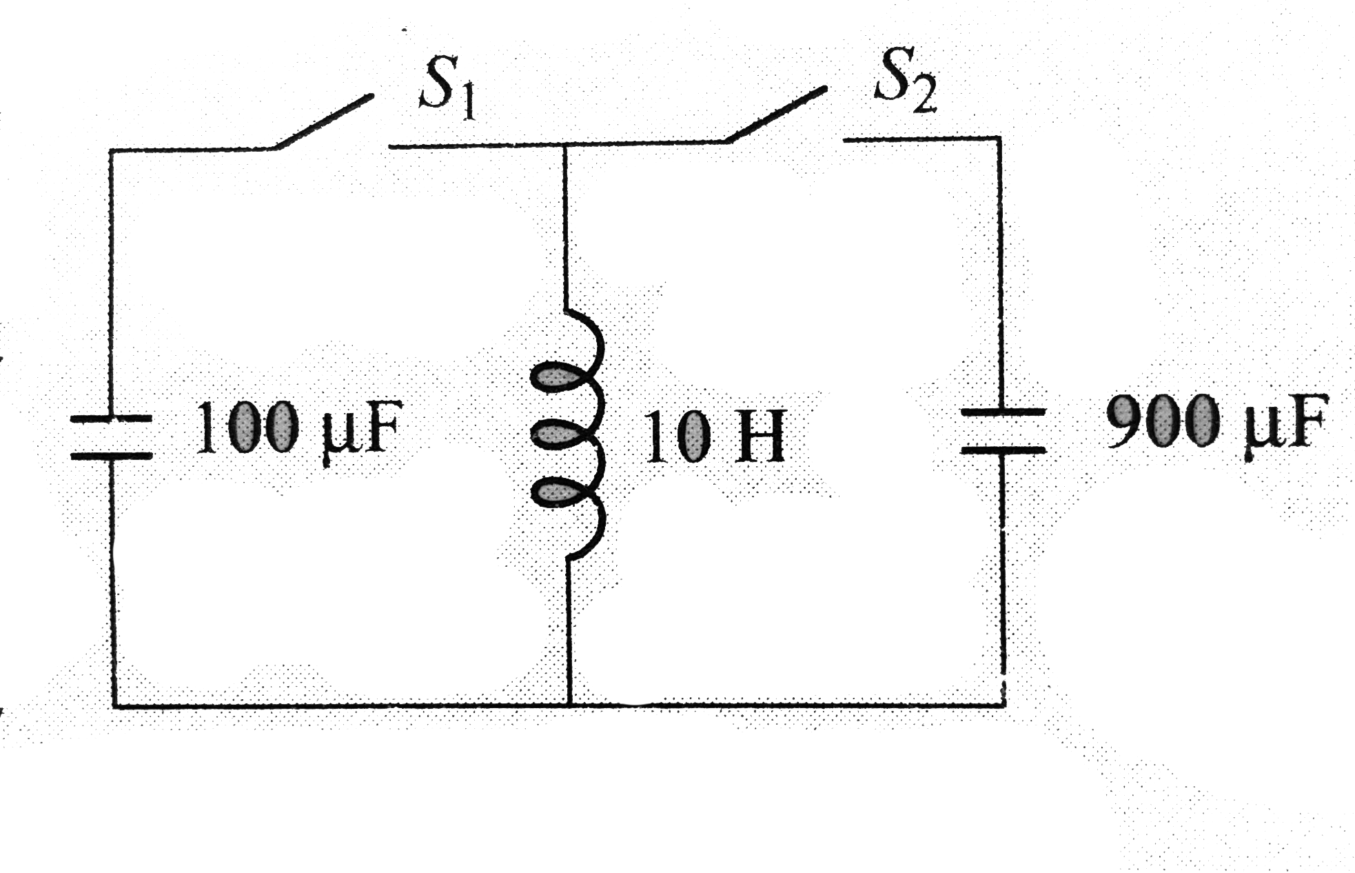 View Solution
Question 17
The circuit shows in Fig. is in the steady state with switch S1 closed. At t=0,S1 is opened and switch S2 is closed.
a. Derive expression for the charge on capacitor C2 as a function of time.
b. Determine the first instant t, when the energy in the inductor becomes one-third of that in the capacitor.
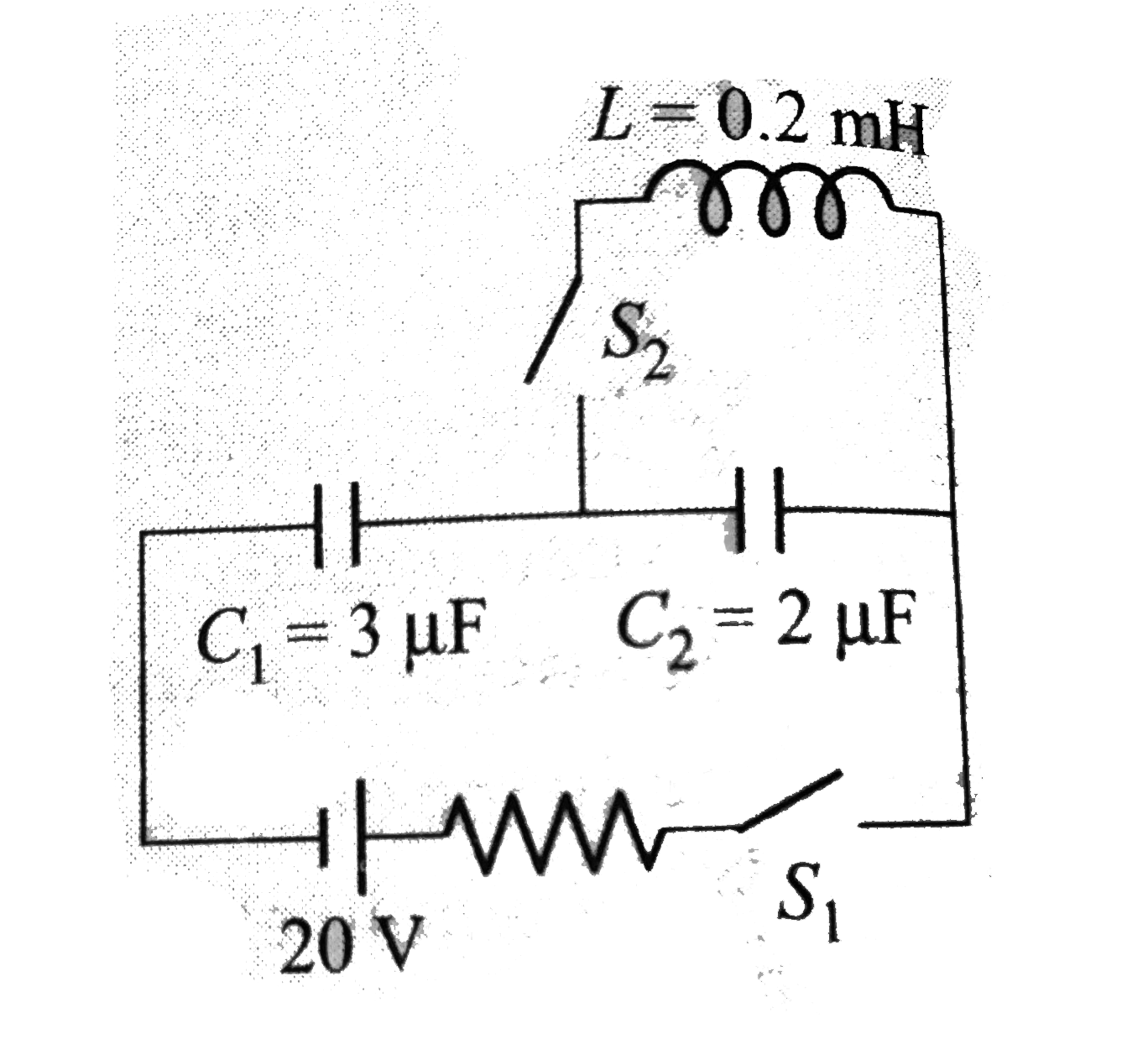 View Solution
Question 19
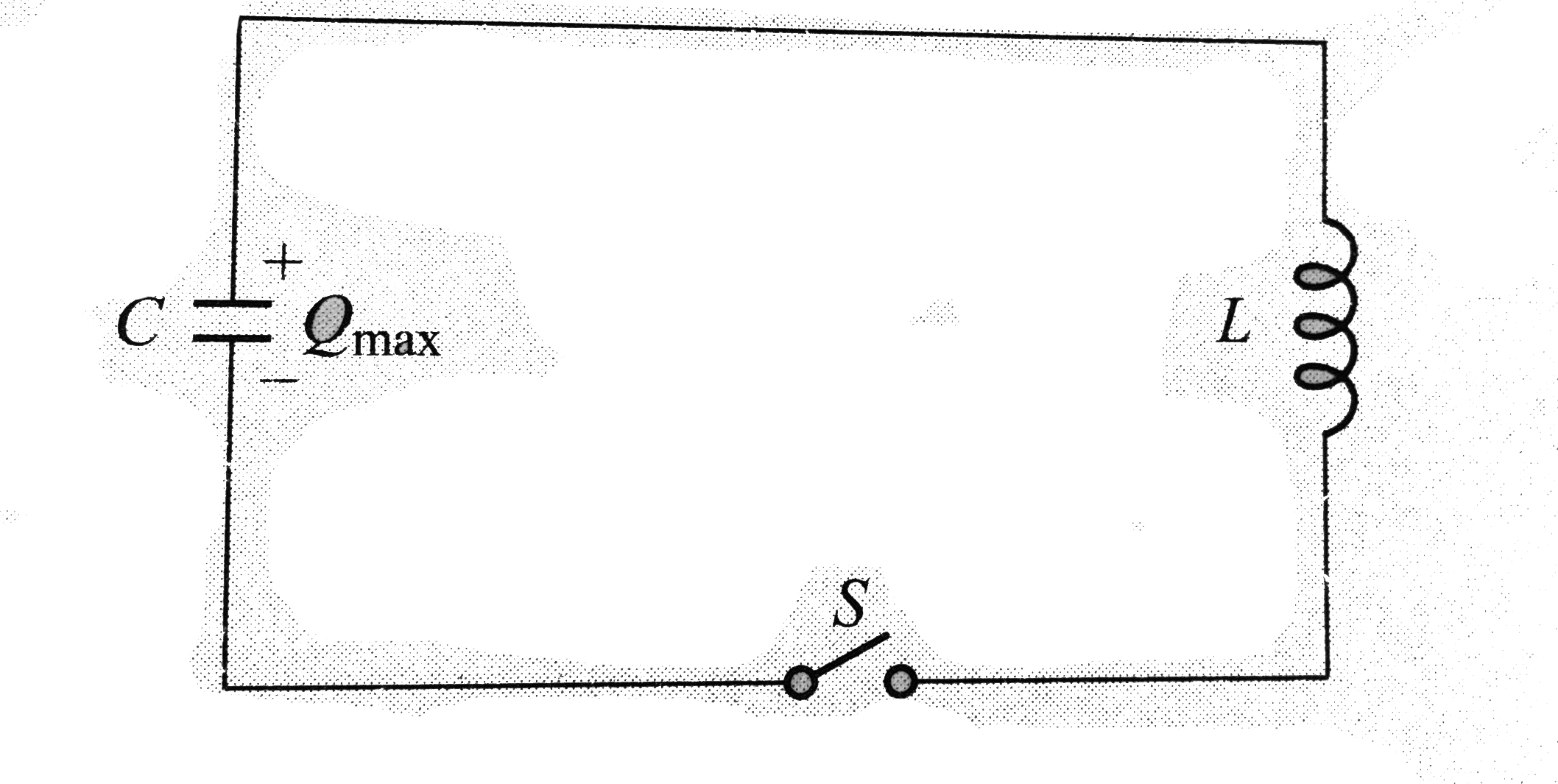
An inductor of inductance 2.0mH is connected across a charged capacitor of capacitance 5.0μF and the resulting L−C circuit is set oscillating at its natural frequency. Let Q denotes the instantaeus charge on the capacitor and I the current in the circuit. It is found that the maximum value of Q is 200μC. View SolutionQuestion 20
A metal bar AB can slide on two parallel thick metallic rails separated by a distance l. A resistance R and an inductance L are connected to the rails as shown in the figure. A long straight wire carrying a constant current I0 is placed in the plane of the rails and perpendicular to them as shown. The bar AB is held at rest at a distance x0 from the long wire. At t=0, it is made to slide on the rails away from wire. Answer the following questions.
(a) Find a relation among i,didtanddϕdt, where i is the current in the circuit and ϕ is the flux of the megnetic field due to the long wire through the circuit.
(b) It is observed that at time t=T, the metal bar AB si at a distance of 2x0 from the long wire and the resistance R carries a current (i1). Obtain an expression for the net charge that has flown through riesistance R form t=0 to t=T.
(c) THe bar is suddenly stopped at time T. THe current through resistance R is found to be i14 at time 2T. Find the value of LR in terms of hte other given quantities.
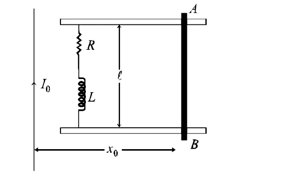 View Solution
Question 21
A circuit containing a two position switch S is shown in figure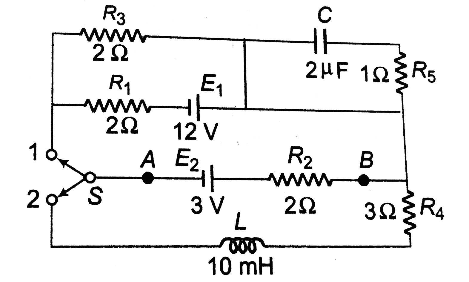
a. The switch S is in position 1. Find the potential differecne VA−VB and the rte of production of joule heat in R1
b. If now the switch S is put in position 2 at t=0. Find ltbRrgt i steady current in R4 and ii hte time when current in R4 is half the steady value. Also calculate the energy stored in the inductor L at that time.View SolutionQuestion 22
A metal rod OA of mann 'm' and length 'r' is kept rotating with a constantangular speed ω in a vertical plane about a horizontal axis at the end O. The free end A is arraged to slide without friction along fixed conduction circular ring in the same plane as that of rotation. A uniform and constant magnetic induction →B is applied perpendicular and into the plane of rotation as shown in the figure below. An inductor L and an external resistance R are connected through a swithch S between the point O and a point C on the ring to form an electrical circuit. Neglect the resistance of the ring and the rod. Initially, the switch is open.
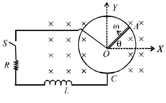
(a) What is the induced emf across the teminal of the switch?
(b) The switch S is closed at time t=0.
(i) Obtain an expression for the current as a function of time.
(ii) In the steady state, obtin the time dependence of the torque required to maintain the constant angular speed, given that the rod OA was along th positive X-axis at t=0.View Solution
All Exercises from CENGAGE PHYSICS (ENGLISH) Class 12 PHYSICS INDUCTANCE
- ARCHIVES (FILLS IN THE BLANKS)
- ARCHIVES (INTEGER)
- ARCHIVES (LINKED COMPRESHENSION)
- ARCHIVES (MULTIPLE CORRECT)
- ARCHIVES (SINGLE CORRECT )
- COMPREHENSION TYPE
- CONCEPT BASED
- EXERCISE 4.1
- EXERCISES (ASSERTION-REASONING)
- EXERCISES (INTEGER)
- EXERCISES (LINKED COMPRESHENSION)
- EXERCISES (MULTIPLE CORRECT )
- EXERCISES (SINGLE CORRECT )
- EXERCISES (SUBJECTIVE)
- MULTIPLE CORRECT ANSWER
- SINGLE CORRECT ANSWER TYPE
- SUBECTIVE TYPE
- ILLUSTRATION
- SOLVED EXAMPLES


