Comprehension Type from CENGAGE PHYSICS (ENGLISH) Chapter 17 MISCELLANEOUS VOLUME 3 for Class 12
| Class 12 | PHYSICS |
| Chapter | MISCELLANEOUS VOLUME 3 |
| CENGAGE PHYSICS (ENGLISH) | Comprehension Type |
| Medium | English |
| Academic Year | 2023-2024 |
Question 1
We know that electric field (E ) at any point in space can be calculated using the relation
→E=−δVδxˆi−δVδyˆj−δVδzˆk
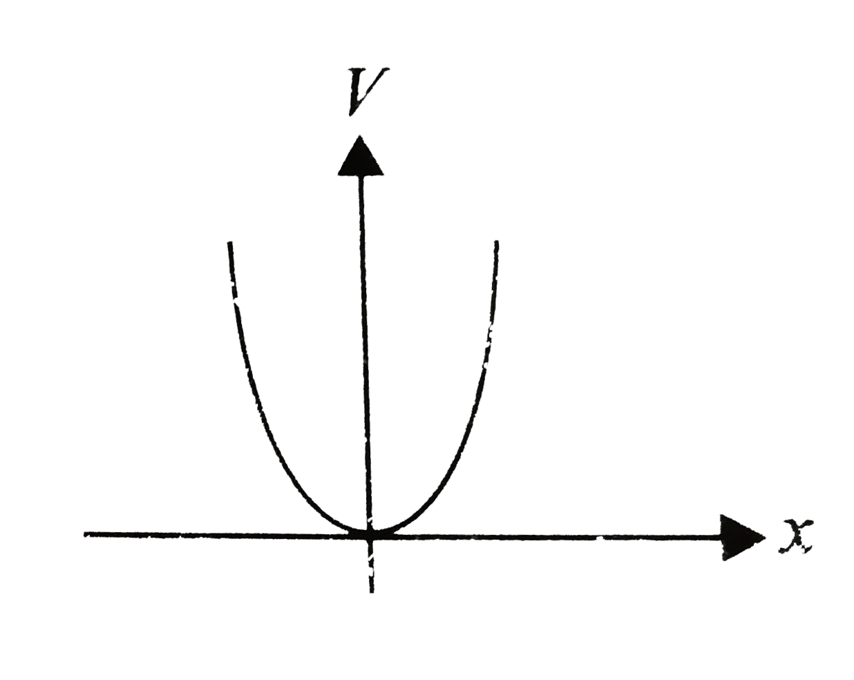
if we know the variation of potential (V) at that point. Now let the electric potential in volt along the x-axis vary as V=2x2, where x is in meter. Its variation is as shown in figure
Draw the variation of electric field (E ) along the x-axis. View SolutionQuestion 2
We know that electric field (E ) at any point in space can be calculated using the relation
→E=−δVδxˆi−δVδyˆj−δVδzˆk
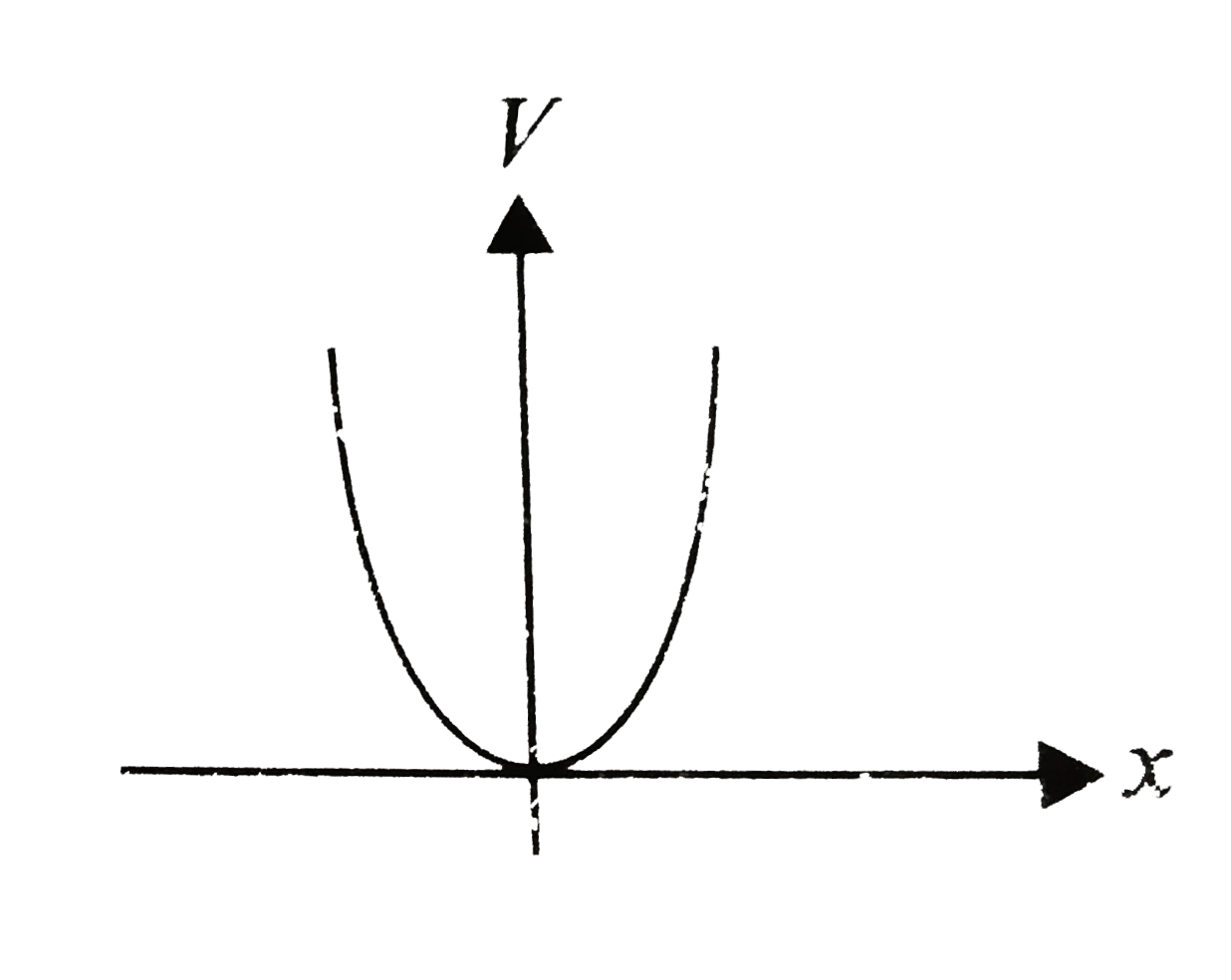
if we know the variation of potential (V) at that point. Now let the electric potential in volt along the x-axis vary as V=2x2, where x is in meter. Its variation is as shown in figure
A charge particle of mass 10 mg and charge 2.5μC is released from rest at x=2m. Find its velocity when it crosses origin. View SolutionQuestion 3
We know that electric field (E ) at any point in space can be calculated using the relation
→E=−δVδxˆi−δVδyˆj−δVδzˆk

if we know the variation of potential (V) at that point. Now let the electric potential in volt along the x-axis vary as V=2x2, where x is in meter. Its variation is as shown in figure
Draw the variation of electric field (E ) along the x-axis. View SolutionQuestion 4
Consider a system of two equal points charges, each Q=8μC, which are fixed at points (2m, 0 ) and (-2m, 0). Another charge μ is held at a point (0,0.1m) on the y-axis. Mass of the charge μ is 91 mg . At t= 0 , μ is released from rest and it is observed to oscillate along y-axis in a simple harmonic manner. It is also observed that at t = 0 , the force experienced by it is 9×10⁻³N.
Charge q is View SolutionQuestion 5
Consider a system of two equal points charges, each Q=8μC, which are fixed at points (2m, 0 ) and (-2m, 0). Another charge μ is held at a point (0,0.1m) on the y-axis. Mass of the charge μ is 91 mg . At t= 0 , μ is released from rest and it is observed to oscillate along y-axis in a simple harmonic manner. It is also observed that at t = 0 , the force experienced by it is 9×10⁻³N.
Amplitude of motion is View SolutionQuestion 6
Consider a system of two equal points charges, each Q=8μC, which are fixed at points (2m, 0 ) and (-2m, 0). Another charge μ is held at a point (0,0.1m) on the y-axis. Mass of the charge μ is 91 mg . At t= 0 , μ is released from rest and it is observed to oscillate along y-axis in a simple harmonic manner. It is also observed that at t = 0 , the force experienced by it is 9×10⁻³N.
Frequency of oscillation is View SolutionQuestion 7
Consider a system of two equal points charges, each Q=8μC, which are fixed at points (2m, 0 ) and (-2m, 0). Another charge μ is held at a point (0,0.1m) on the y-axis. Mass of the charge μ is 91 mg . At t= 0 , μ is released from rest and it is observed to oscillate along y-axis in a simple harmonic manner. It is also observed that at t = 0 , the force experienced by it is 9×10⁻³N.
Equation of SHM (displacement from mean position) can be expressed asView SolutionQuestion 8
In a certain experiments to measure the ratio of charge to mass of elementry particles, a surprising result was obtained in which two particle, a surprising result was obtained in which two particles moved in such a way that the distance between them always remained constant. It was also noticed that this two-particle system was isolated from all other particles and no force was acting on this system except the force between these two mases. After careful observation followed bu intensive calculation, it was deduced that velocity of these two particles was always opposite in direction and magnitude of velocity was 103ms−1and2×103ms−1 for first and second particle, respectively, and mass of these particles were 2×10⁻³⁰kgand10−30kg, respectively. Distance between them were 12Å(1Å = 10^(-10)m).
Acceleration of the first particle was View SolutionQuestion 9
In a certain experiments to measure the ratio of charge to mass of elementry particles, a surprising result was obtained in which two particle, a surprising result was obtained in which two particles moved in such a way that the distance between them always remained constant. It was also noticed that this two-particle system was isolated from all other particles and no force was acting on this system except the force between these two mases. After careful observation followed bu intensive calculation, it was deduced that velocity of these two particles was always opposite in direction and magnitude of velocity was 103ms−1and2×103ms−1 for first and second particle, respectively, and mass of these particles were 2×10⁻³⁰kgand10−30kg, respectively. Distance between them were 12Å(1Å = 10^(-10)m).
Acceleration of the second particle was View SolutionQuestion 10
In a certain experiments to measure the ratio of charge to mass of elementry particles, a surprising result was obtained in which two particle, a surprising result was obtained in which two particles moved in such a way that the distance between them always remained constant. It was also noticed that this two-particle system was isolated from all other particles and no force was acting on this system except the force between these two mases. After careful observation followed bu intensive calculation, it was deduced that velocity of these two particles was always opposite in direction and magnitude of velocity was 103ms−1and2×103ms−1 for first and second particle, respectively, and mass of these particles were 2×10⁻³⁰kgand10−30kg, respectively. Distance between them were 12Å(1Å = 10^(-10)m).
if the first particle is stopped for a moment and then released, the velocity of center of mass of the system just after the release will be View SolutionQuestion 11
In a certain experiments to measure the ratio of charge to mass of elementry particles, a surprising result was obtained in which two particle, a surprising result was obtained in which two particles moved in such a way that the distance between them always remained constant. It was also noticed that this two-particle system was isolated from all other particles and no force was acting on this system except the force between these two mases. After careful observation followed bu intensive calculation, it was deduced that velocity of these two particles was always opposite in direction and magnitude of velocity was 103ms−1and2×103ms−1 for first and second particle, respectively, and mass of these particles were 2×10⁻³⁰kgand10−30kg, respectively. Distance between them were 12Å(1Å = 10^(-10)m).
Paths of the two particles was View SolutionQuestion 14
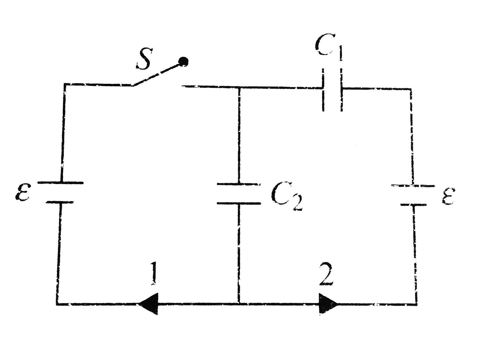
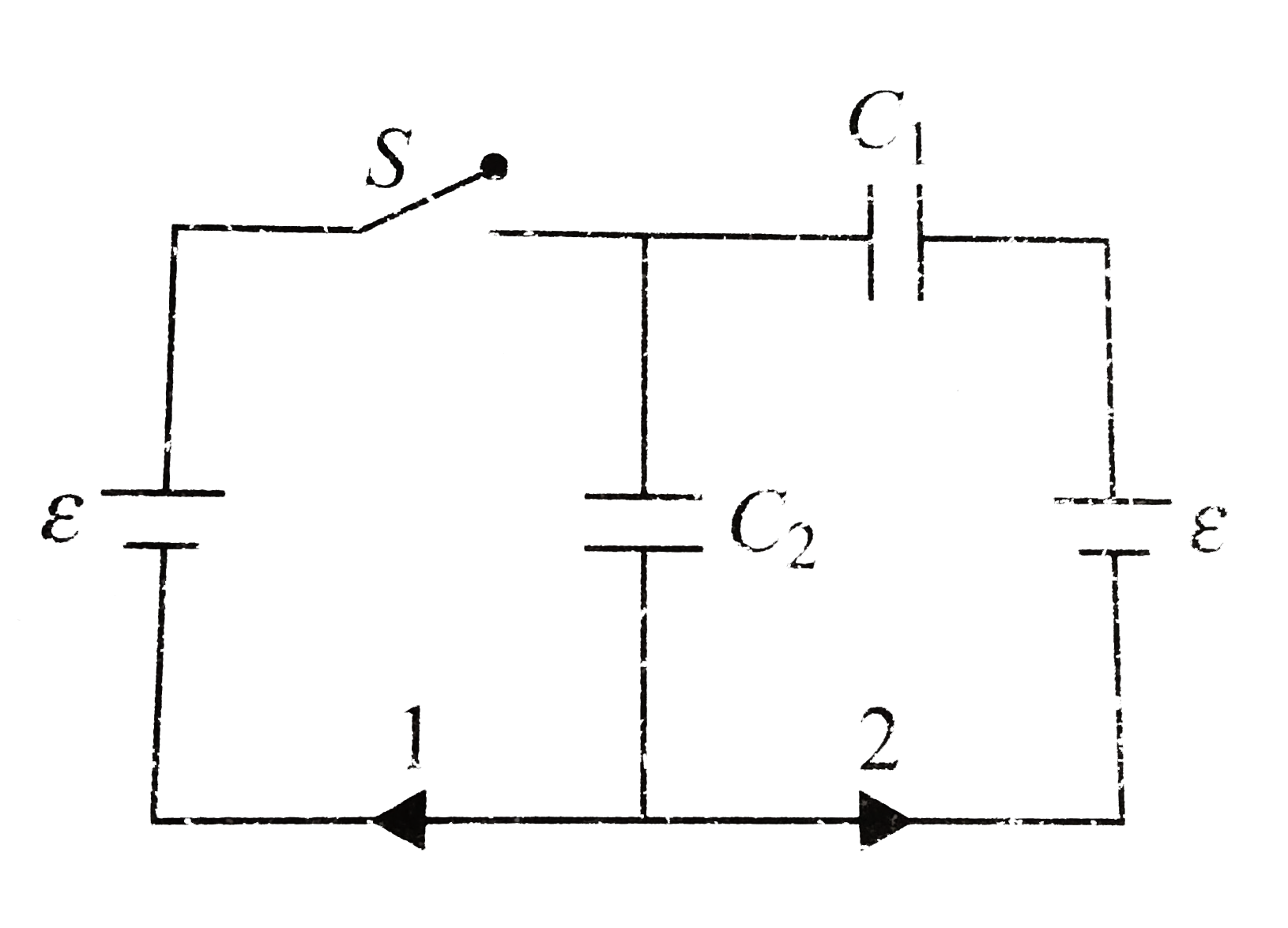
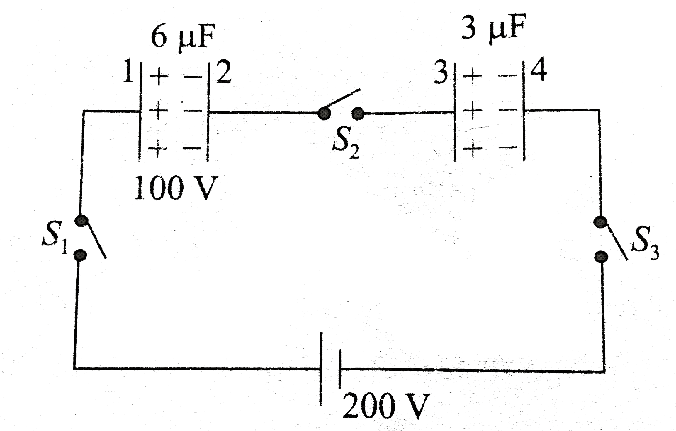
Capacitor C1=2μFandC2=3μF are connected in series to a battery of emf ε=120V whose midpoint is earthed. The wire connecting the capacitors can be earthed through a key K. Now, key K is closed. Determine the charge flowing through the sections 1, 2, and 3 in the directions indicated in figure
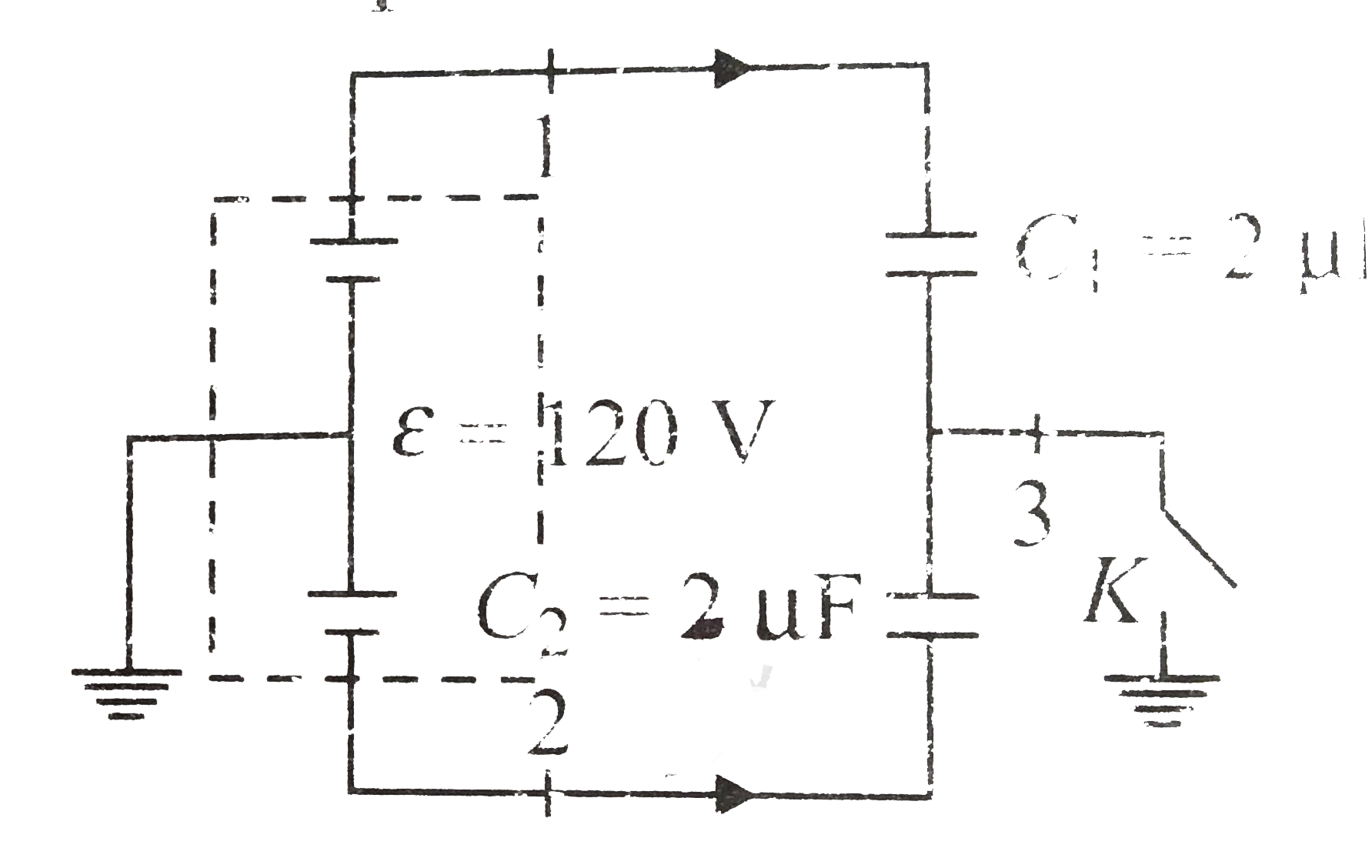
In section 2, View SolutionQuestion 15
Capacitor C1=2μFandC2=3μF are connected in series to a battery of emf ε=120V whose midpoint is earthed. The wire connecting the capacitors can be earthed through a key K. Now, key K is closed. Determine the charge flowing through the sections 1, 2, and 3 in the directions indicated in figure

In section 2, View SolutionQuestion 16
Capacitor C1=2μFandC2=3μF are connected in series to a battery of emf ε=120V whose midpoint is earthed. The wire connecting the capacitors can be earthed through a key K. Now, key K is closed. Determine the charge flowing through the sections 1, 2, and 3 in the directions indicated in figure
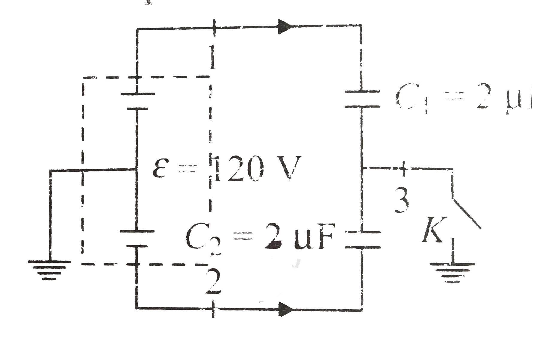
In section 3, View SolutionQuestion 17
A researcher studying the properties of ions in the upper atmosphere wishes to construct an apparatus with the following charateristics: Using an electric field, a beam of ions, each having charge q, mass m , and initial velocity vˆi, is turned through an angle of 90∘ as each ion undergoes displacement Rˆi+Rˆj. The ions enter a chamber as shown in figure and leave through the exit port with the same speed they had when they entered the chamber. The electric field acting on the ions is to have constant magnitude.
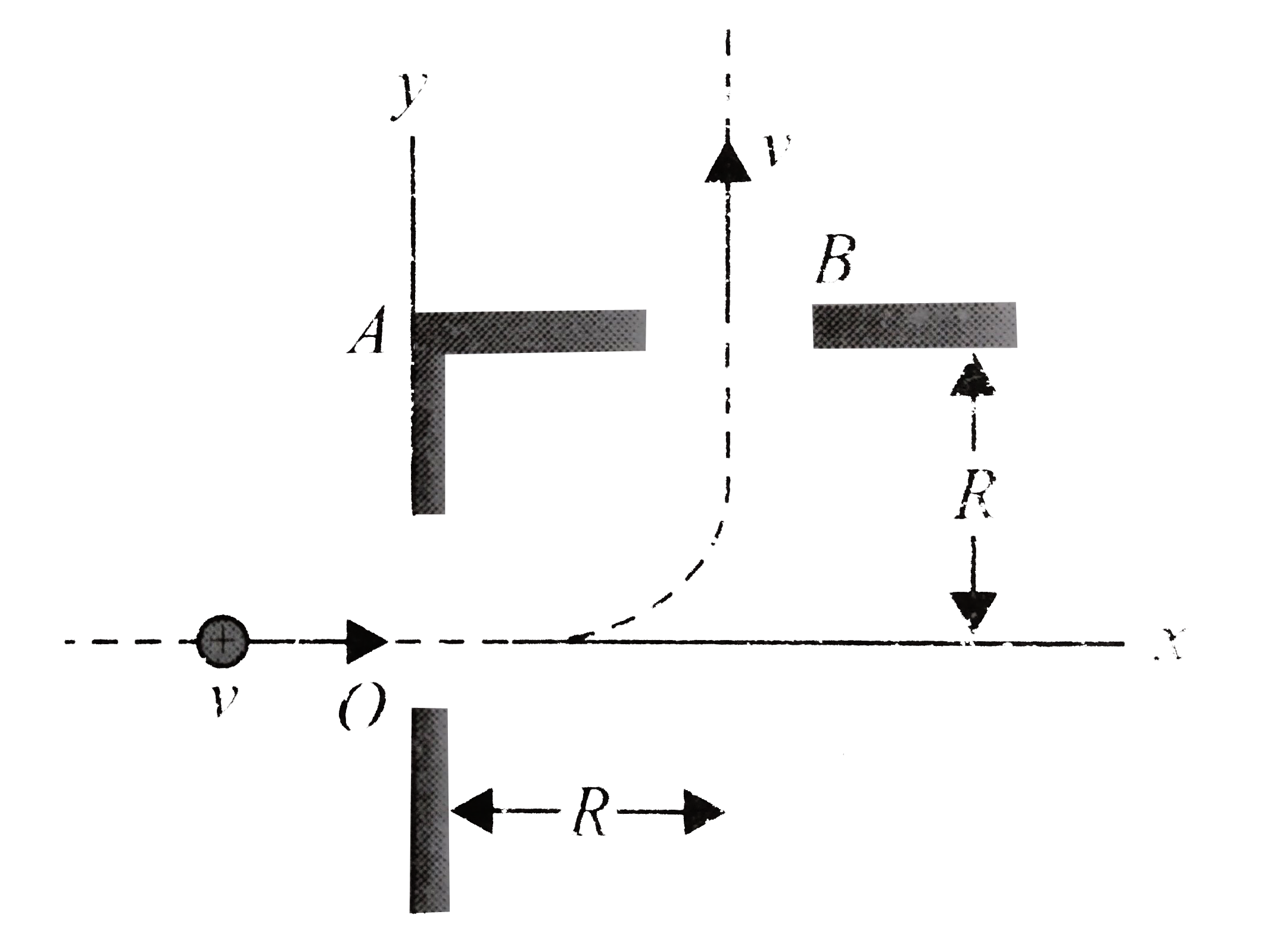
Suppose the electric field is produced by two concentric cylindrical electrodes not shown in the diagram, and hence is radial. What magnitude should the field have? View SolutionQuestion 18
A researcher studying the properties of ions in the upper atmosphere wishes to construct an apparatus with the following charateristics: Using an electric field, a beam of ions, each having charge q, mass m , and initial velocity vˆi, is turned through an angle of 90∘ as each ion undergoes displacement Rˆi+Rˆj. The ions enter a chamber as shown in figure and leave through the exit port with the same speed they had when they entered the chamber. The electric field acting on the ions is to have constant magnitude.
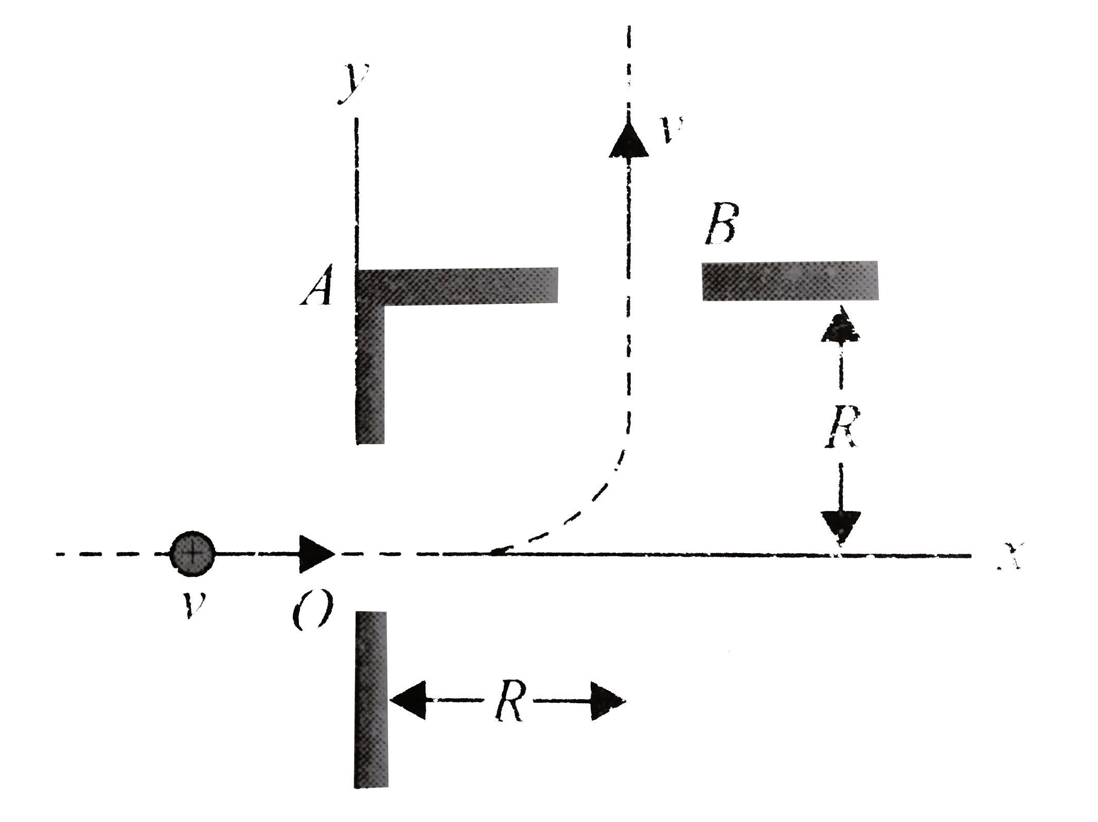
If the field is produced by two flat plates and is uniform in direction, what value should the field have in this case? View SolutionQuestion 20
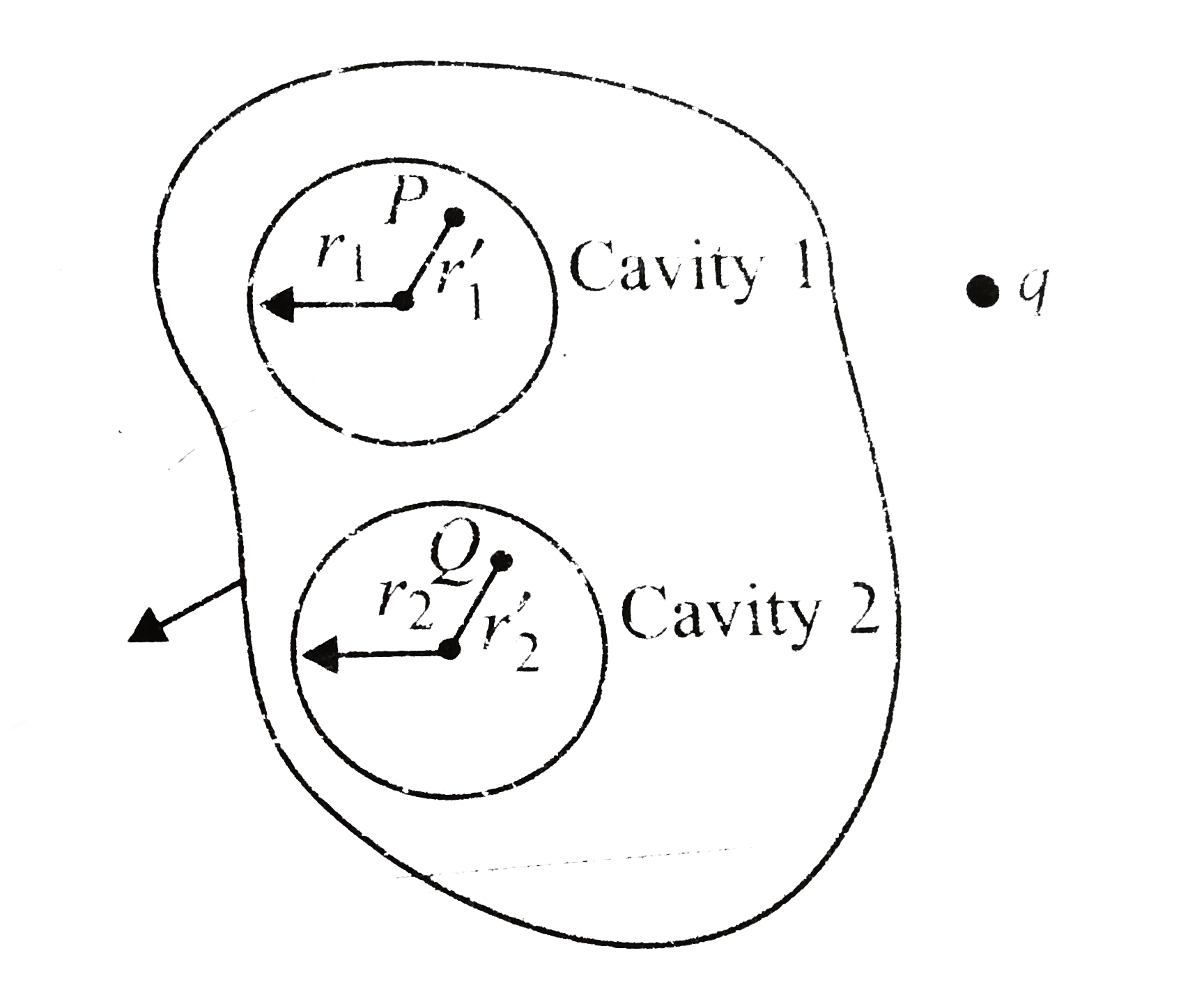
A point charge q1 is placed inside cavity 1 and another point charge q2 is inside cavity 2. A point charge q is placed outside the conductor. For the situation described above, answer the following questions.
→E inside the conductor at point S distant r from point charge q, due to charge on outer surface of the conductor, would be View SolutionQuestion 21
A point charge q1 is placed inside cavity 1 and another point charge q2 is inside cavity 2. A point charge q is placed outside the conductor. For the situation described above, answer the following questions.
→E inside the conductor at point S distant r from point charge q, due to charge on outer surface of the conductor, would be View SolutionQuestion 22
A point charge q1 is placed inside cavity 1 and another point charge q2 is inside cavity 2. A point charge q is placed outside the conductor. For the situation described above, answer the following questions.
If charge q2 is at point Q (inside cavity 2), then →E at the center of cavity 2 due to induced charge on the surface of cavity 2 would be View SolutionQuestion 23
A point charge q1 is placed inside cavity 1 and another point charge q2 is inside cavity 2. A point charge q is placed outside the conductor. For the situation described above, answer the following questions.
If the potential of the conductor is V0 and charge q2 is placed at the center of cavity 2, then potential at point Q is View SolutionQuestion 24
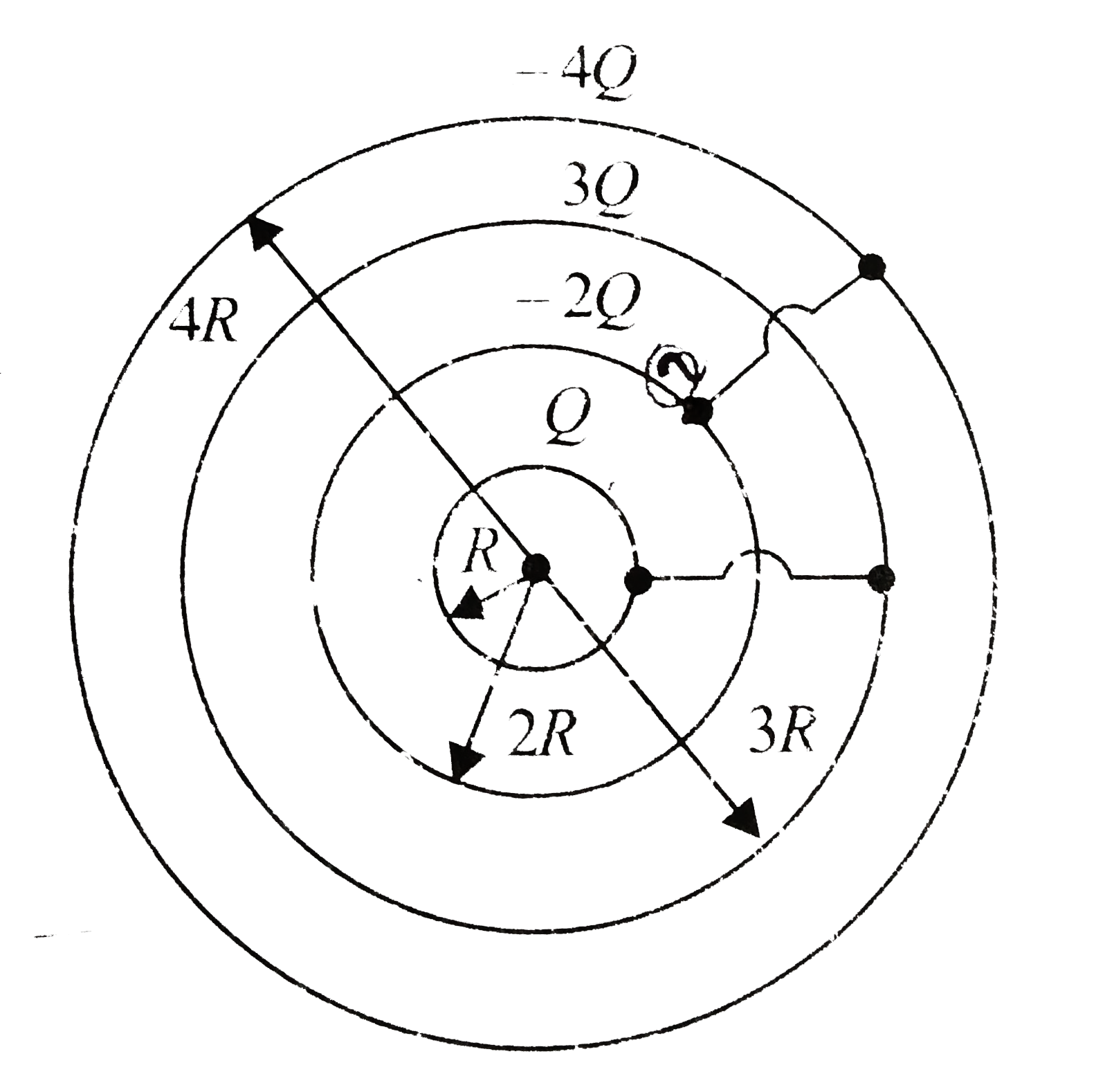
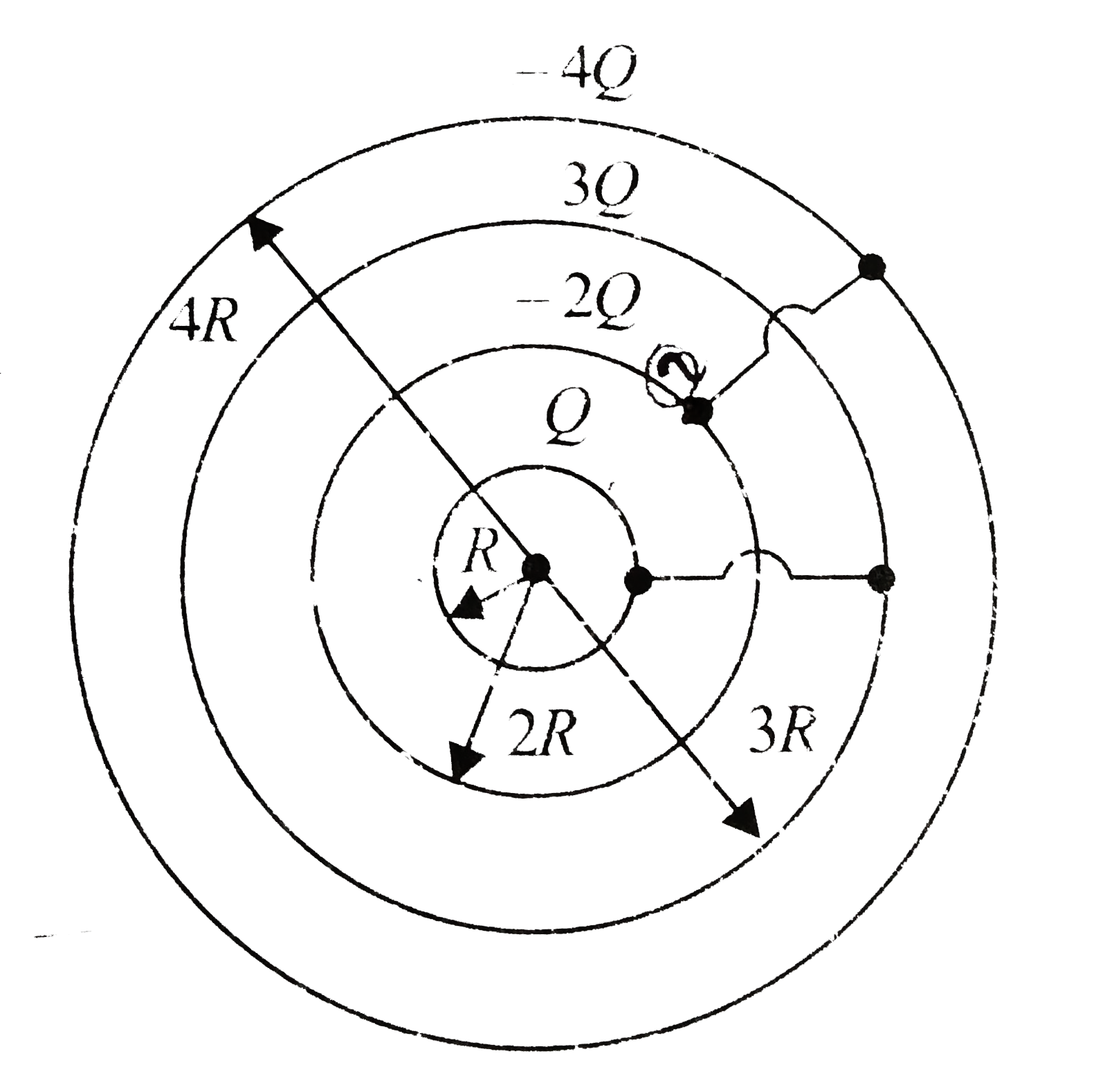
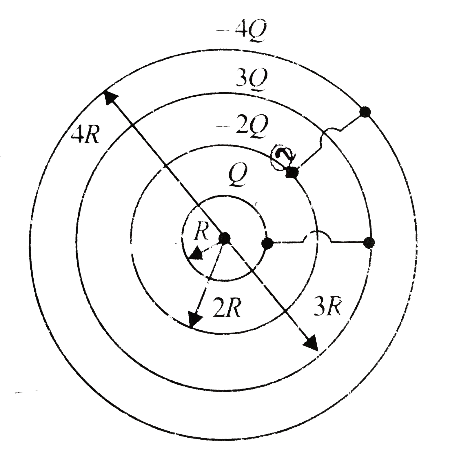
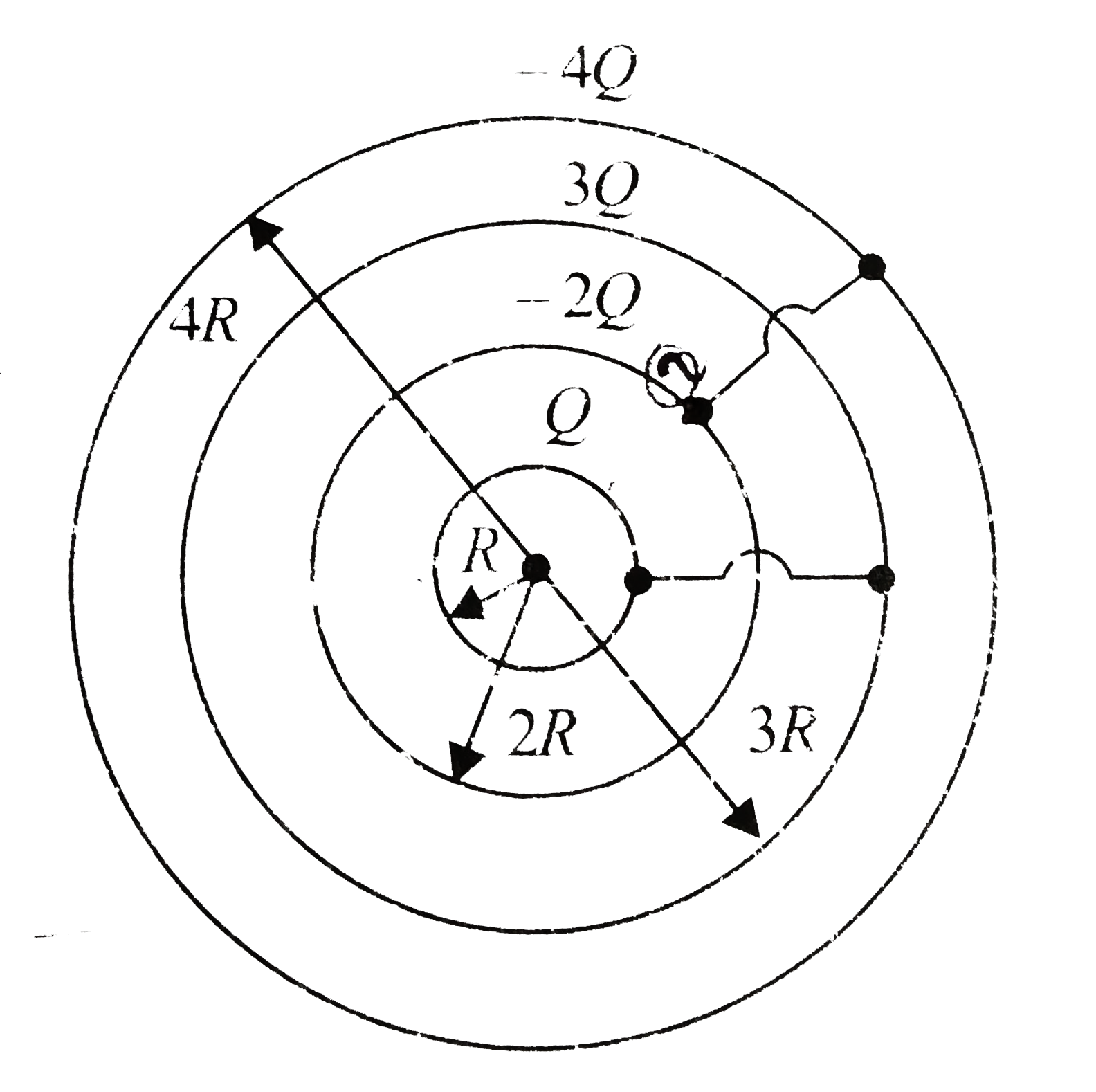
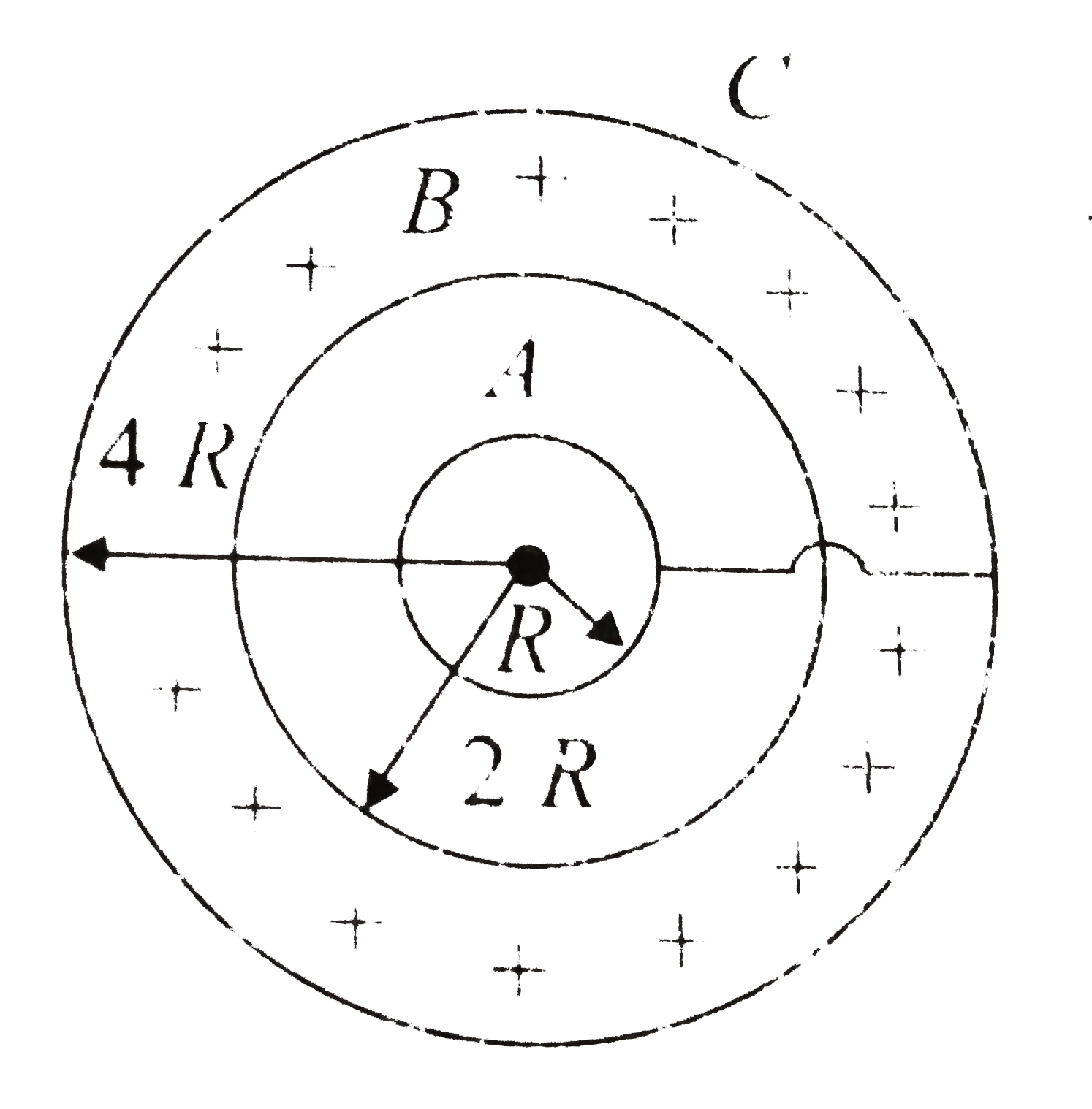
Four concentric hollow spheres of radii R, 2R, 3R, and 4R are given the charges as shown in figure. Then the conductors 1 and 3, 2 and 4 are connected by conducting wires (both the connections are made at the same time.)
 ,
,
The charge on the inner surface of the third conductor is View SolutionQuestion 29
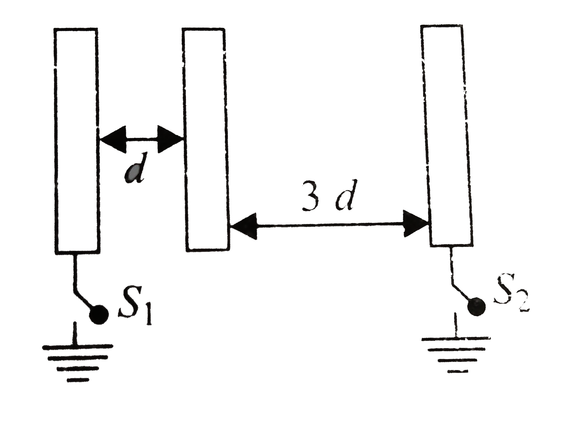
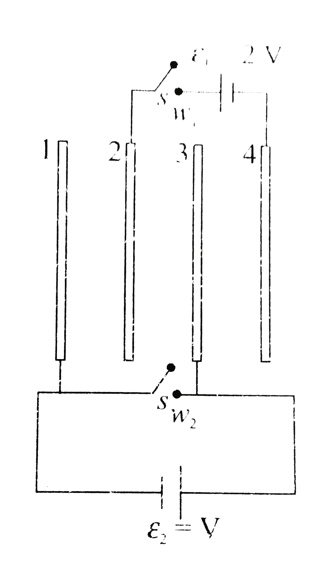
Three metallic plates out of which the middle is given charge Q as shown in the figure. The outer plates can be earthed with the help of switches S1andS2 . The area of each plates is the same. Answer the following question based on the given passage.
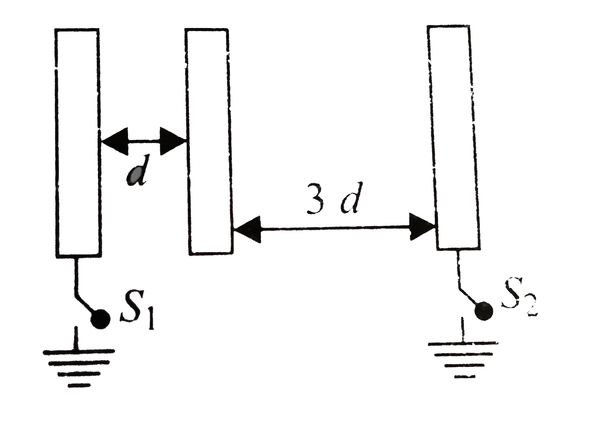
The charge that will flow to the earth when only switch S1 is connected to the earth is View SolutionQuestion 30
Three metallic plates out of which the middle is given charge Q as shown in the figure. The outer plates can be earthed with the help of switches S1andS2 . The area of each plates is the same. Answer the following question based on the given passage.
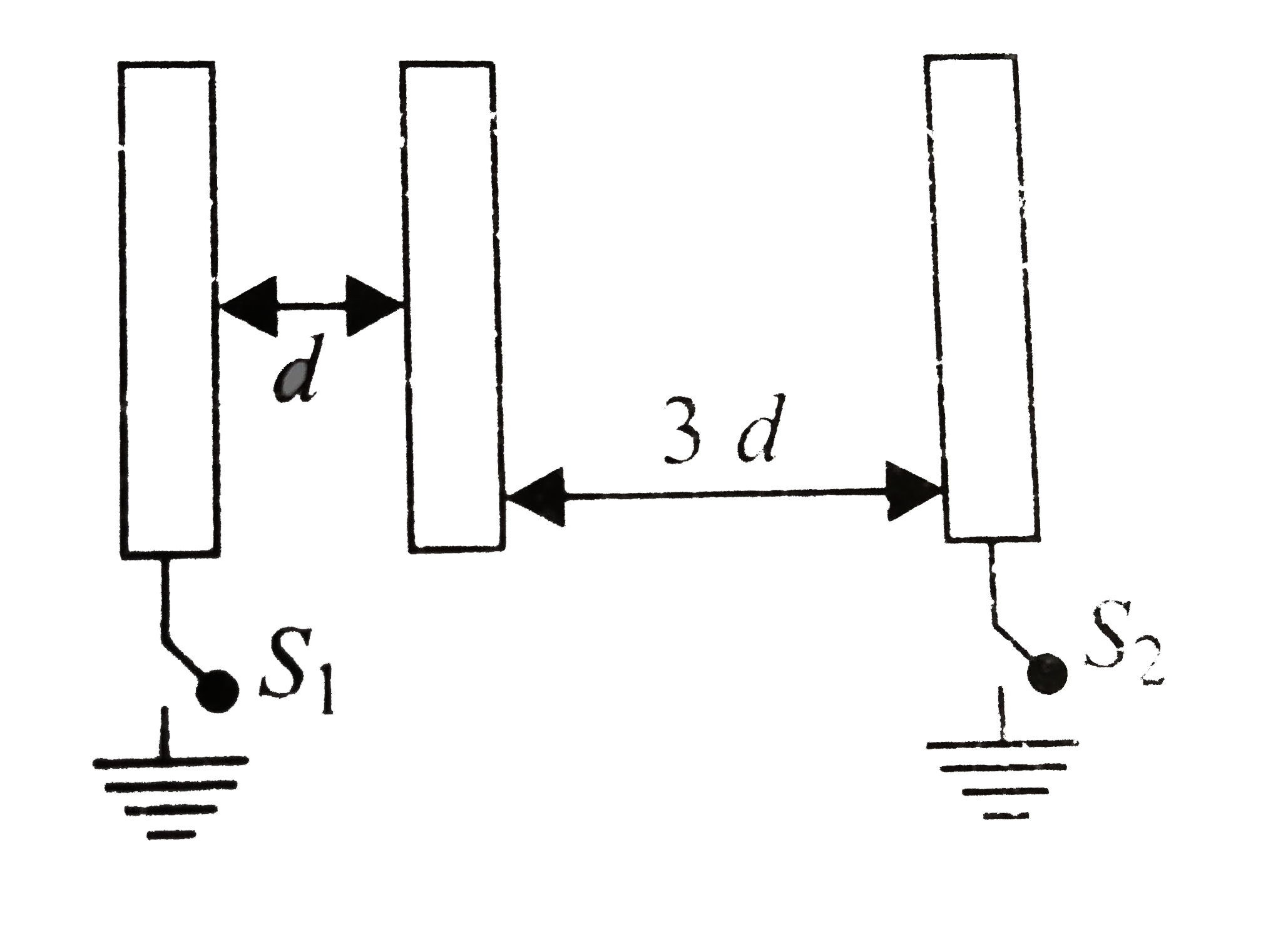
The charge that will flow to the earth through S2 when both switches S1andS2 are grounded simultaneously is View SolutionQuestion 37
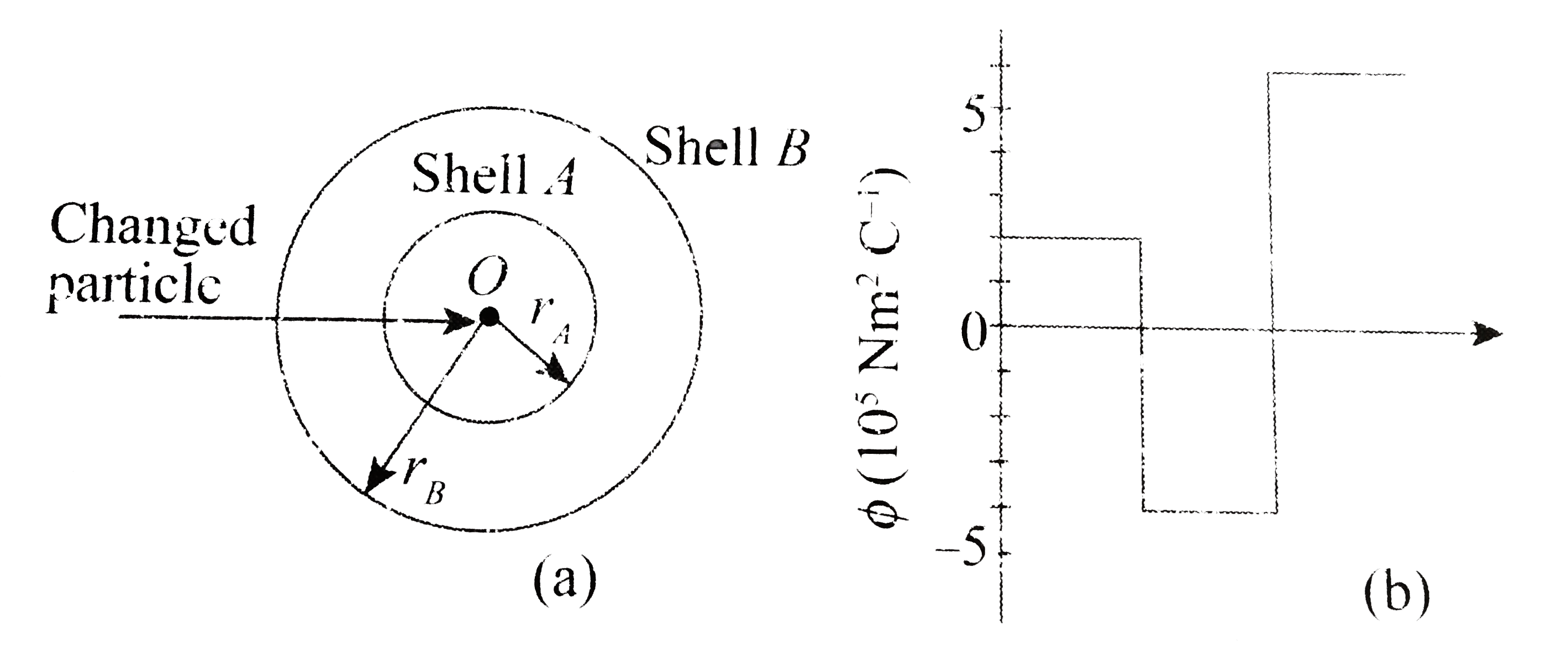
A charged particle is suspended at the center of two thin concentric spherical charged shells, made of nonconducting material. Figure shows cross section of the arrangement. Figure (b) gives the net flux ϕ through a Gaussian sphere centered on the particle, as a function of the radius r of the sphere.
 ,
,
What is the charge on the central particle? View SolutionQuestion 38
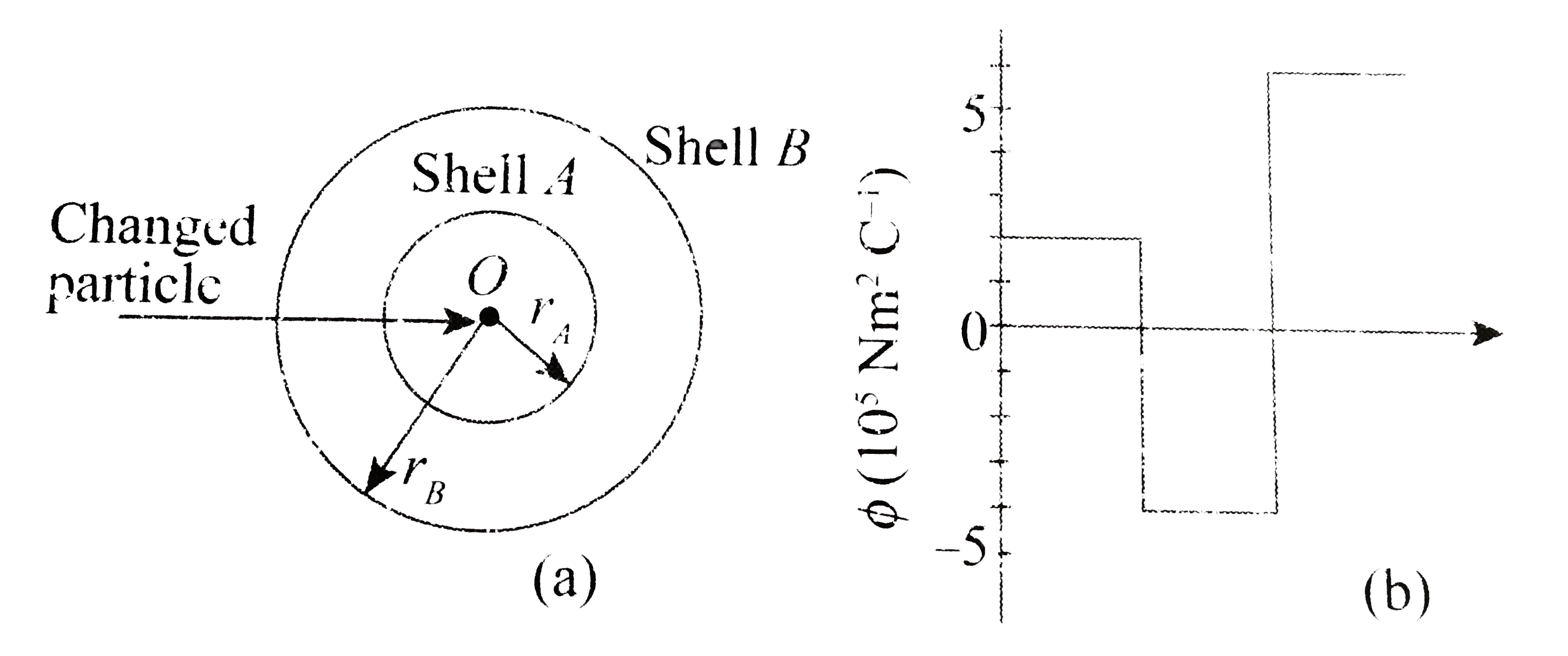
A charged particle is suspended at the center of two thin concentric spherical charged shells, made of nonconducting material. Figure shows cross section of the arrangement. Figure (b) gives the net flux ϕ through a Gaussian sphere centered on the particle, as a function of the radius r of the sphere.
 ,
,
What is the charge on shell A? View SolutionQuestion 39
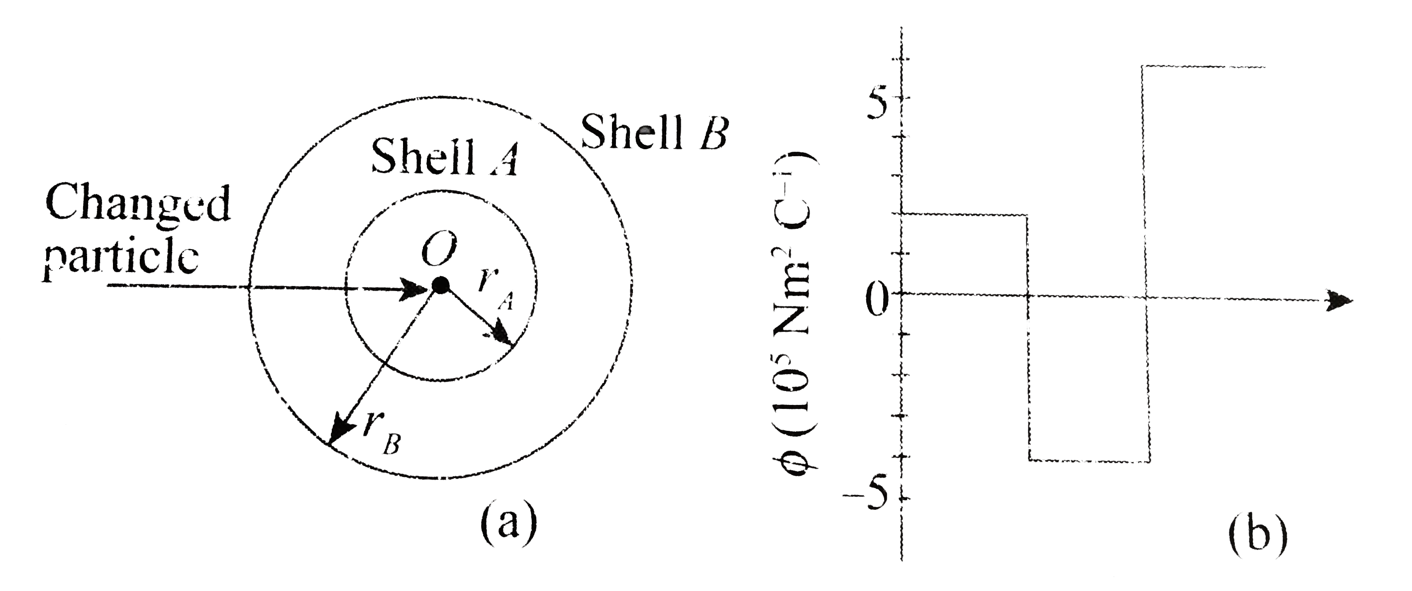
A charged particle is suspended at the center of two thin concentric spherical charged shells, made of nonconducting material. Figure shows cross section of the arrangement. Figure (b) gives the net flux ϕ through a Gaussian sphere centered on the particle, as a function of the radius r of the sphere.
 ,
,
In which range of the values of r is the electric field zero? View SolutionQuestion 41
Capacitor C3 in the circuit is a variable capacitor (its capacitance can be varied). Graph is plotted between potential difference V1 (across capacitor C1) versus C3. Electric potential V1 approaches to 10 V as C3→∞. Given that C1+C2=10μF

The capacitance of the capacitor C1 value View SolutionQuestion 42
Capacitor C3 in the circuit is a variable capacitor (its capacitance can be varied). Graph is plotted between potential difference V1 (across capacitor C1) versus C3. Electric potential V1 approaches to 10 V as C3→∞. Given that C1+C2=10μF

The capacitance of the capacitor C1 value View SolutionQuestion 43
In a region , an electroc field E=10NC−1 making an angle of θ=30∘ with the horizontal plane is present. Coefficient of restitution between ball and surface is e=0.2. Ball has charge q=−2C over it and mass m = 2 kg . Ball is projected at an angle of θ=30∘ with the horizontal with speed u=10ms−1
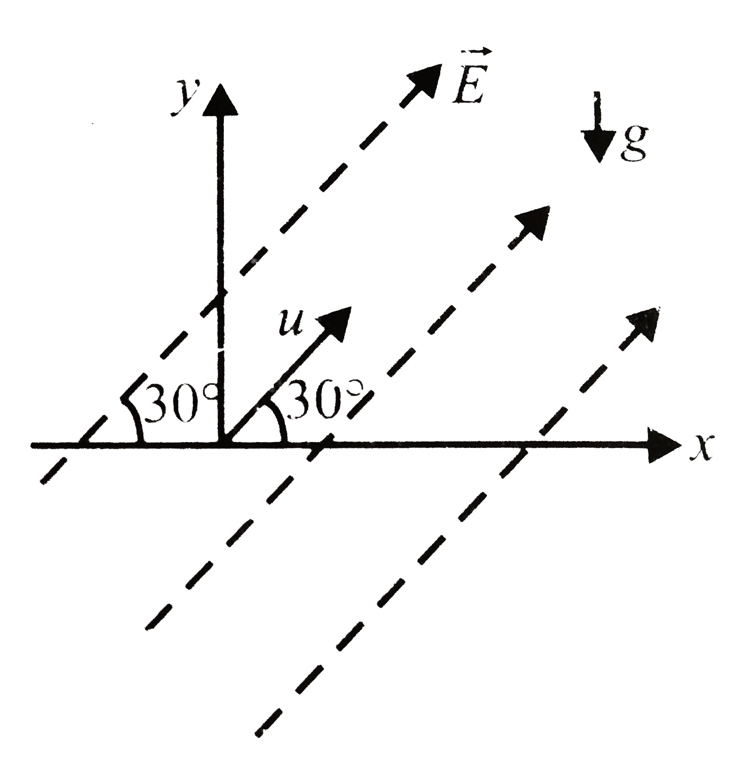
Horizontal distance traveled up to first rebound is View SolutionQuestion 44
In a region , an electroc field E=10NC−1 making an angle of θ=30∘ with the horizontal plane is present. Coefficient of restitution between ball and surface is e=0.2. Ball has charge q=−2C over it and mass m = 2 kg . Ball is projected at an angle of θ=30∘ with the horizontal with speed u=10ms−1
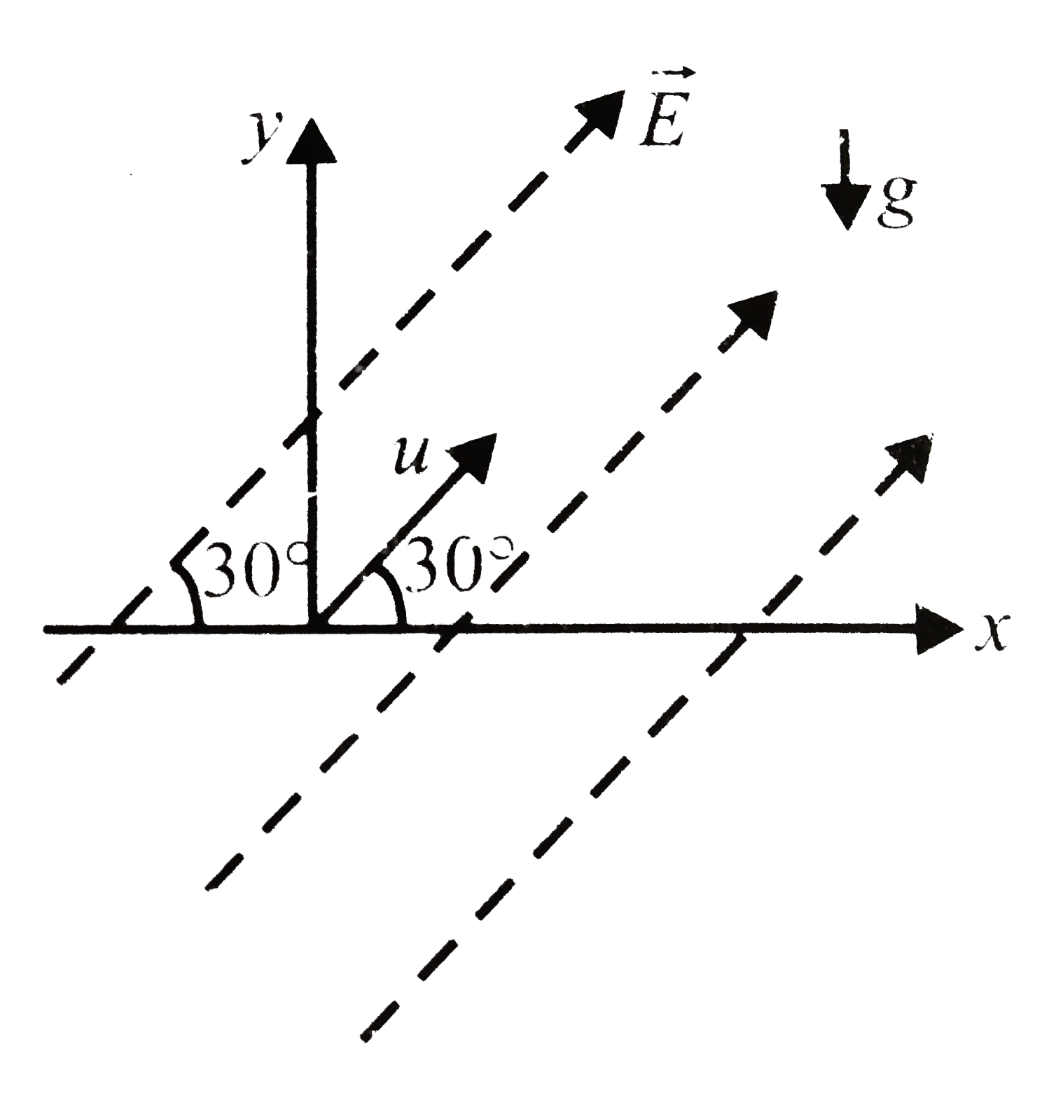
After first impact with the ground, View SolutionQuestion 45
Two circular rings A and B each of radius a = 30 cm are placed coaxially with their axis horizontal in a uniform electric field E=105NC−1 directed vertically upward as shown in figure. Distance between centers of the rings A and B (CAandCB)is40cm. Ring A has positive charge qA=10μC and B has a negative charge qB=−20μC. A particle of mass m and charge q=10μC is released from rest at the center of ring A. If particle moves along CACB, then
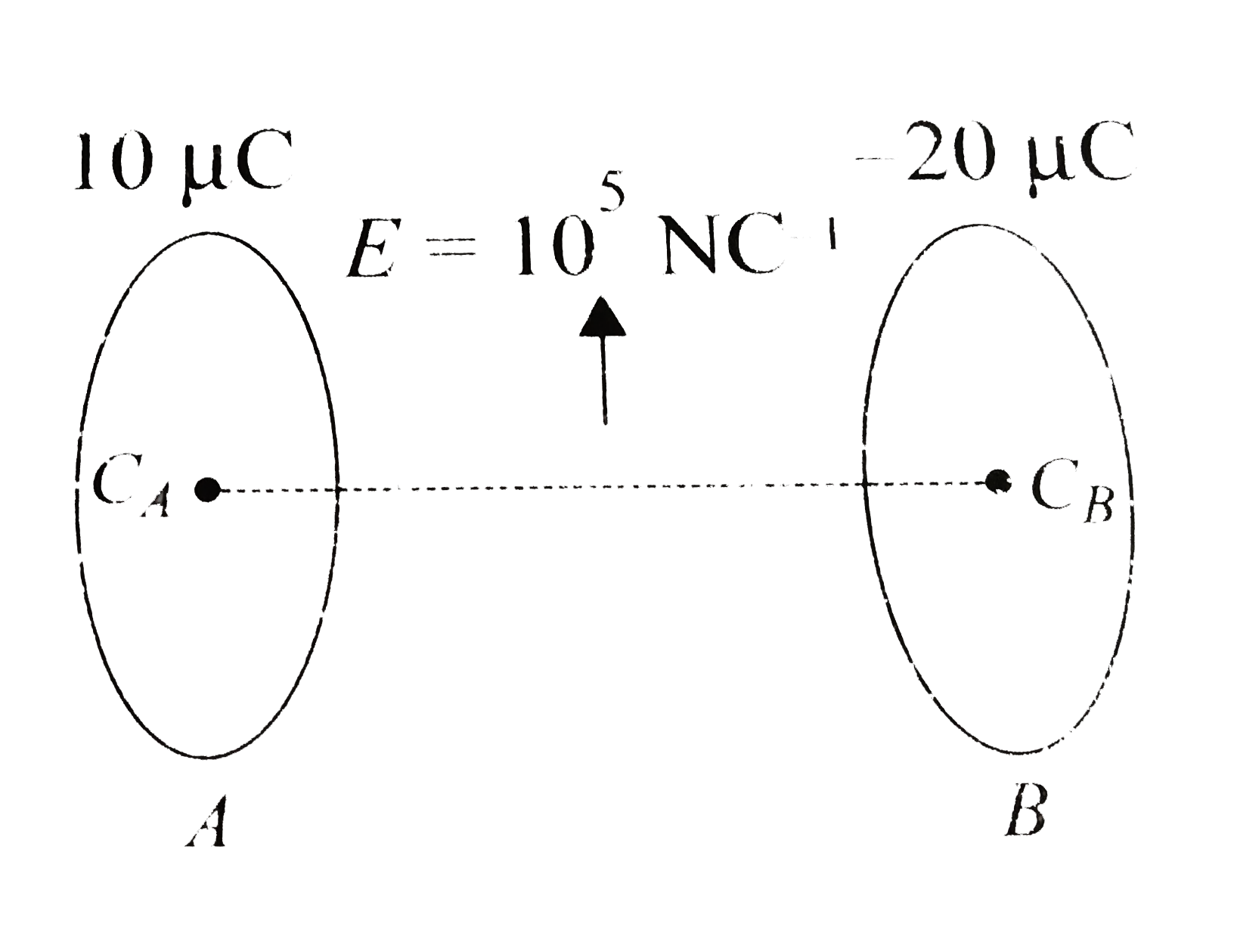
Work done by electric field, when particle moves from CA→CB is View SolutionQuestion 46
Two circular rings A and B each of radius a = 30 cm are placed coaxially with their axis horizontal in a uniform electric field E=105NC−1 directed vertically upward as shown in figure. Distance between centers of the rings A and B (CAandCB)is40cm. Ring A has positive charge qA=10μC and B has a negative charge qB=−20μC. A particle of mass m and charge q=10μC is released from rest at the center of ring A. If particle moves along CACB, then
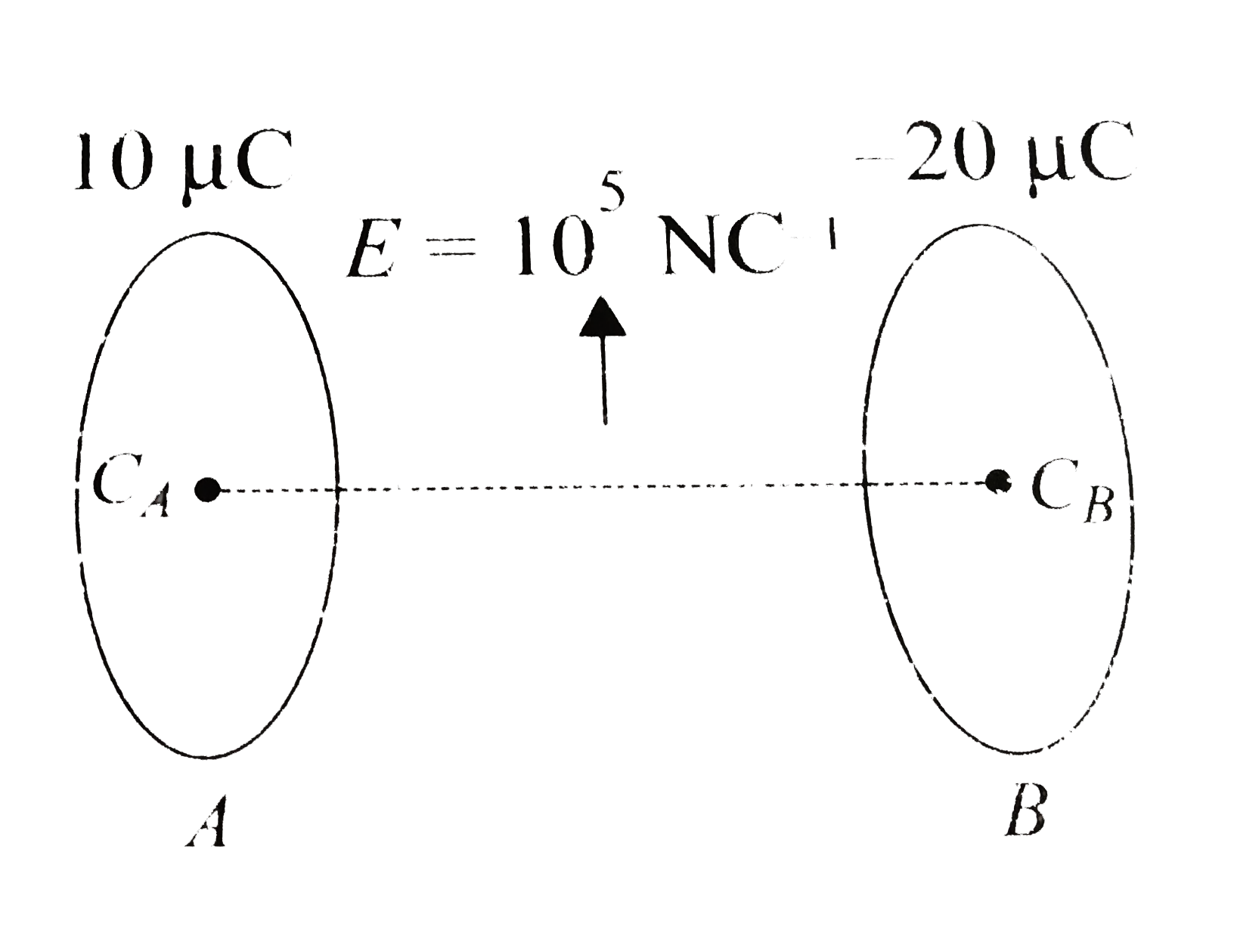
Speed of particle when it reaches at center of B is View SolutionQuestion 49
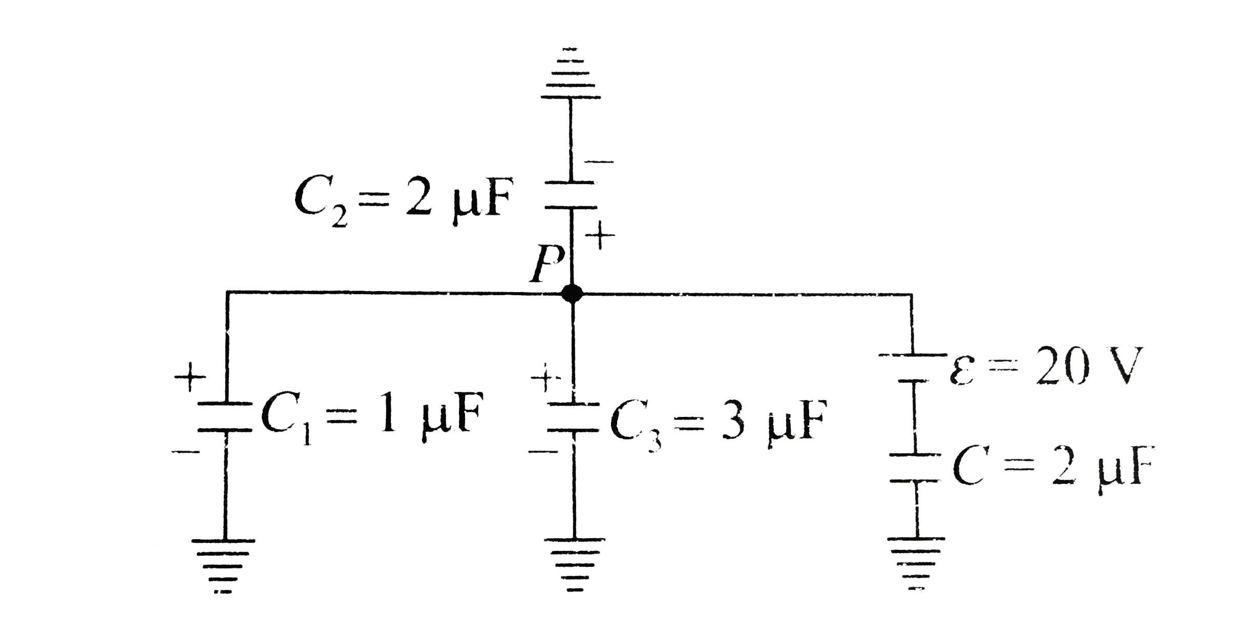
Three capacitors C1,C2,andC3 of capacitance 1μF,2μF,and3μF, respectively, are charged separately as shown in the figure. Now these charged capacitors are connected to a battery of ε=20V and an uncharged capacitor of C=2μF as shown in figure.
 ,
, 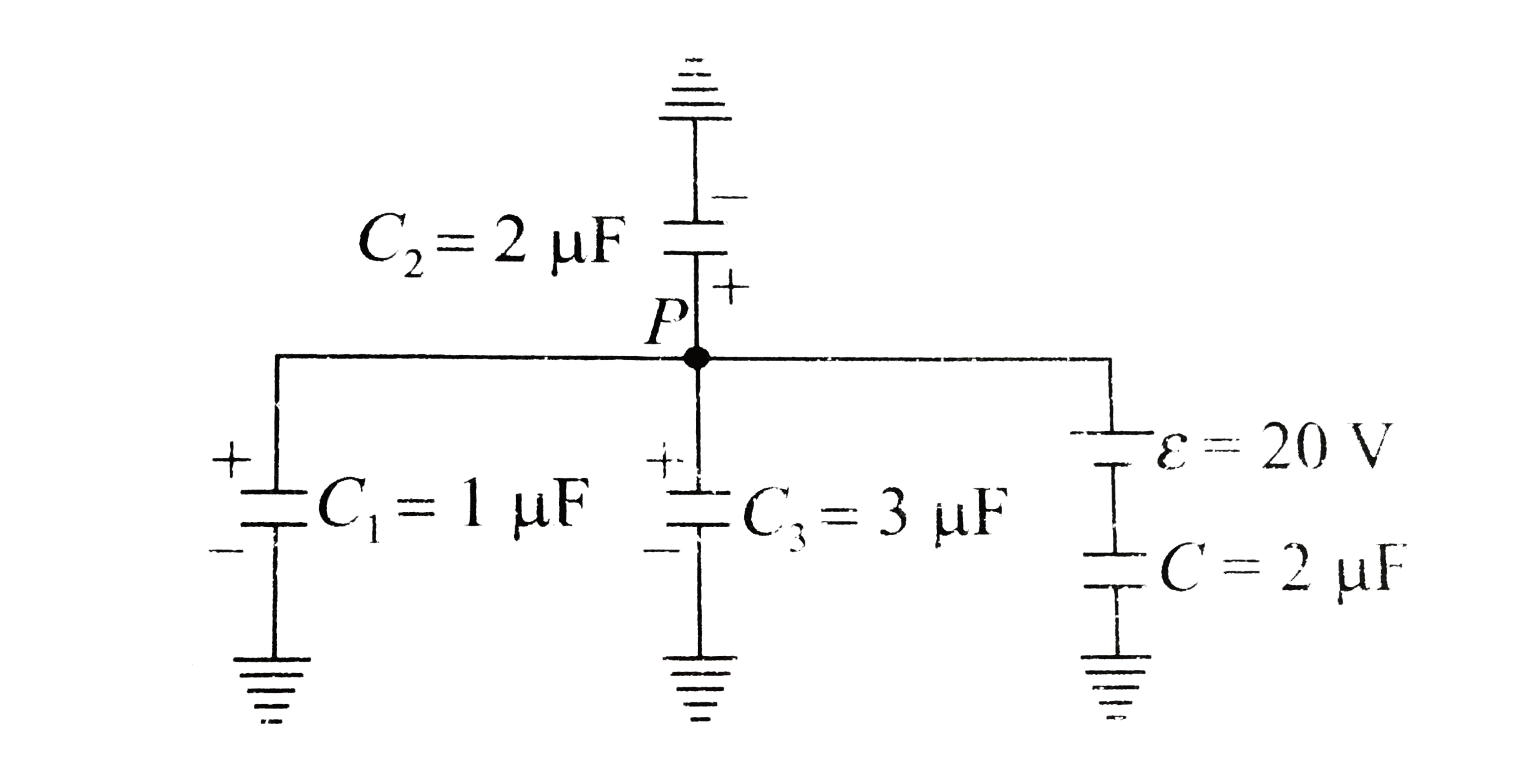
The charge on capacitor marked C is View SolutionQuestion 52
Two points charges are placed on x-axis as shown, a = 1 cm, q=1μC , mass of each particle m=6g. The charges are tied at the end of an inextensible string of length 2a. The whole system is free to move on a horizontal frictionless surface.
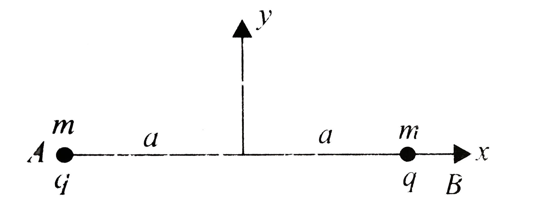
Now suppose a third charge of equal value +q is fixed at the point (a/2,0) and the system of charges A and B is released. There is no friction between third charge and string. Find the maximum velocity of the system of charges A and B. View SolutionQuestion 54
Two nonconducting plates A and B of radii 2R and 4R, respectively, are kept at distance x and 2x from the point charge q. A surface cutout of a nonconducting shell A is kept such that is center coincides with the point charge. Each plate and spherical surface carries surface charge density σ.
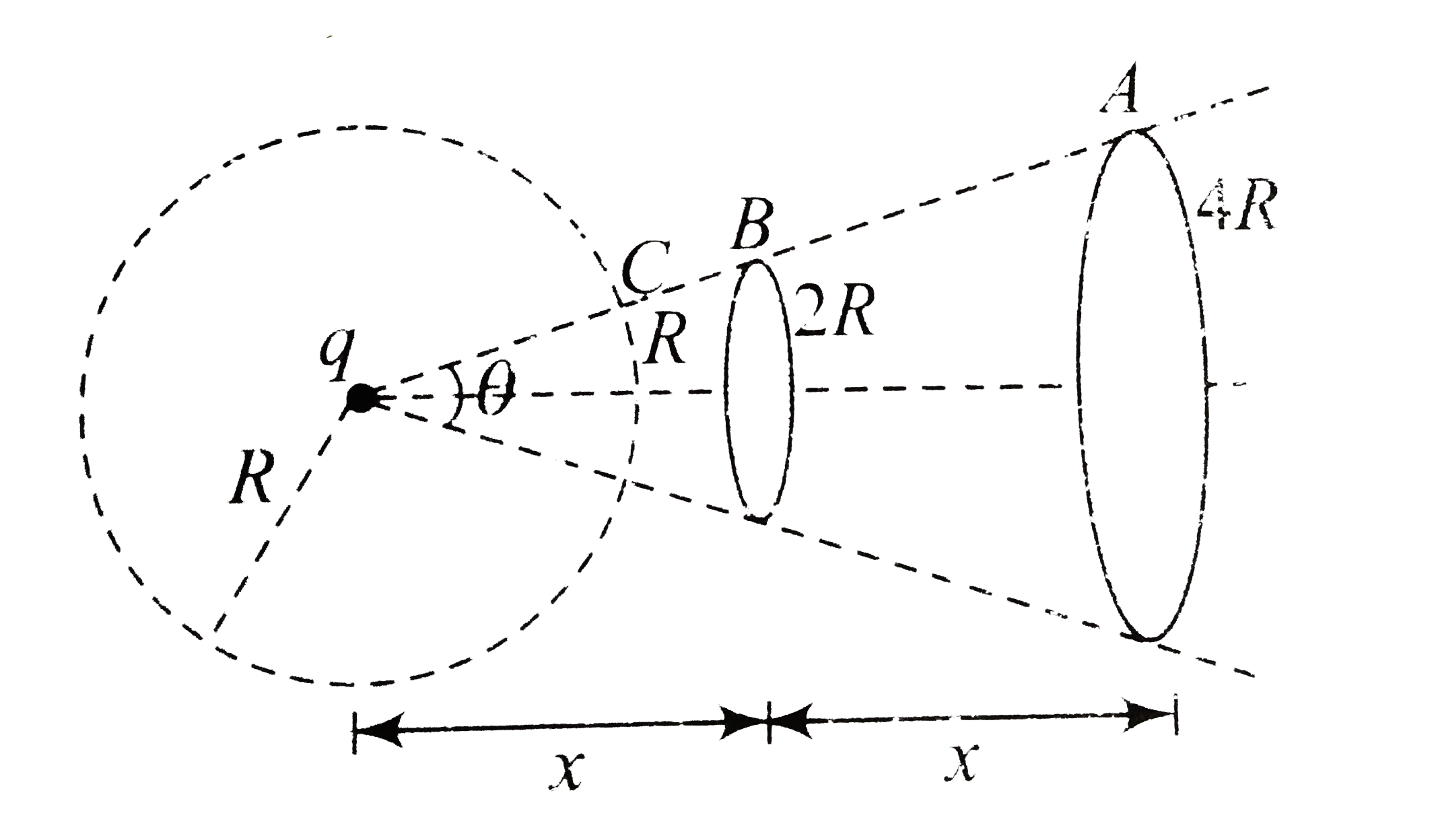
If FA,FB,andFC are the forces on plate A, plate B, and spherical surface C due to charge q, respectively, then View SolutionQuestion 55
Two nonconducting plates A and B of radii 2R and 4R, respectively, are kept at distance x and 2x from the point charge q. A surface cutout of a nonconducting shell A is kept such that is center coincides with the point charge. Each plate and spherical surface carries surface charge density σ.
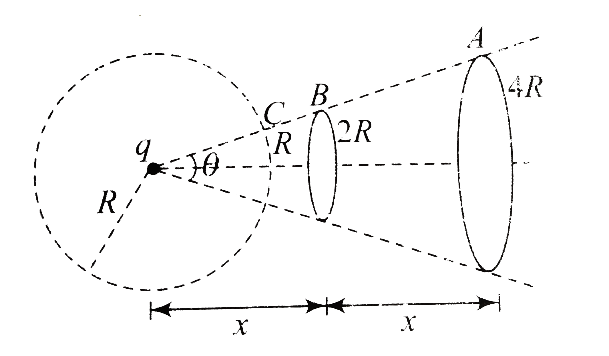
If ϕ1 is flux through surface of (B) due to electric field to (A) and ϕ2 is the flux through (A) due to electric field of (B), then View SolutionQuestion 56
Two nonconducting plates A and B of radii 2R and 4R, respectively, are kept at distance x and 2x from the point charge q. A surface cutout of a nonconducting shell A is kept such that is center coincides with the point charge. Each plate and spherical surface carries surface charge density σ.
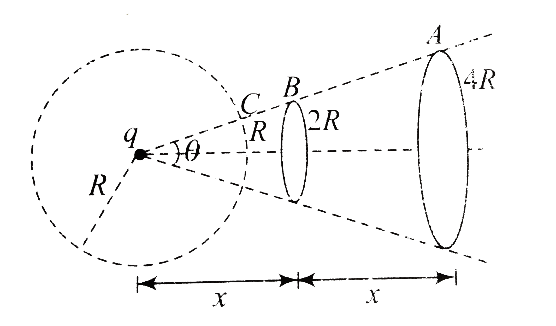
If distance x and radius R are doubled so that FA becomes F'A and FB becomes F'B, then the correct option is View SolutionQuestion 57
Two very large parallel disks of charge have their centers on the x-axis and their planes perpendicular to the x-axis. The disk that intersects x = -R has uniform positive surface charge density +σ, the disk that intersects x=+R has uniform negative surface charge density −σ. (i)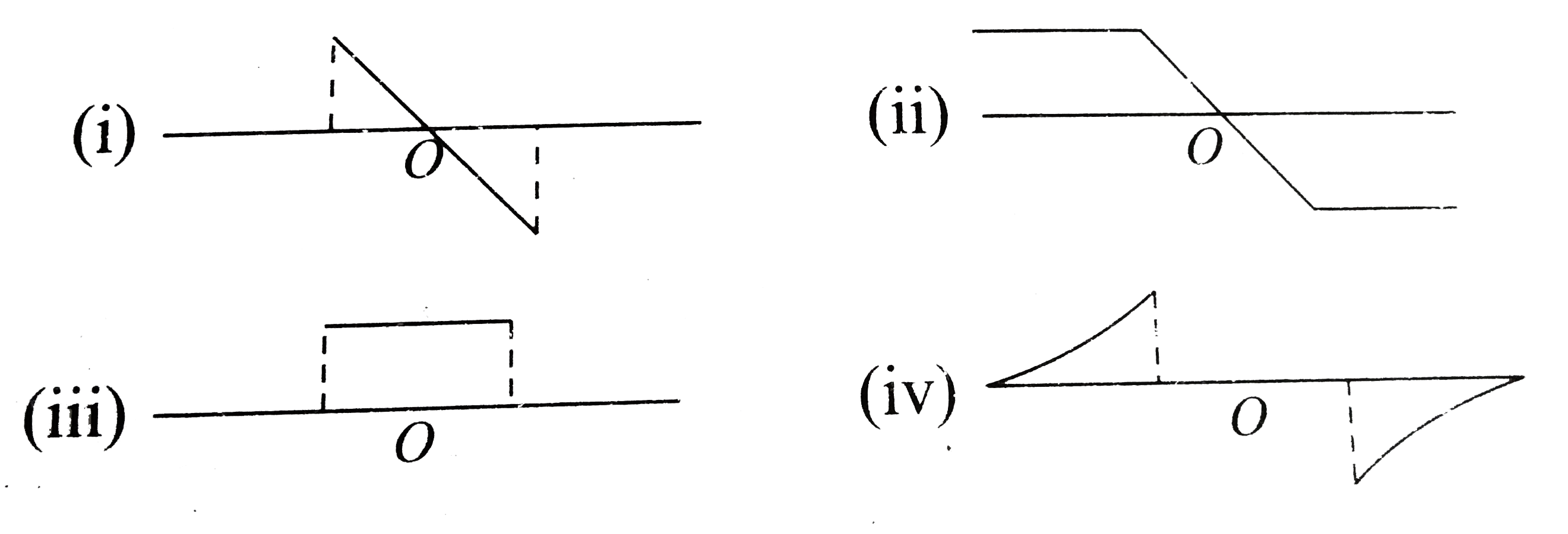 ,
,
Which graph best represents the plot of the x-component of the electric field vector on the x-axis? View SolutionQuestion 60
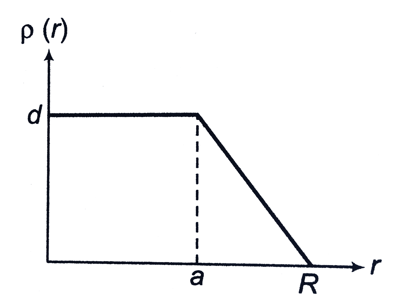
The nuclear charge (Ze) is non uniformlly distribute with in a nucleus of radius r. The charge density ρ(r) (charge per unit volume) is dependent only on the radial distance r form the centre of the nucleus s shown in figure. The electric field is only along the radial direction.
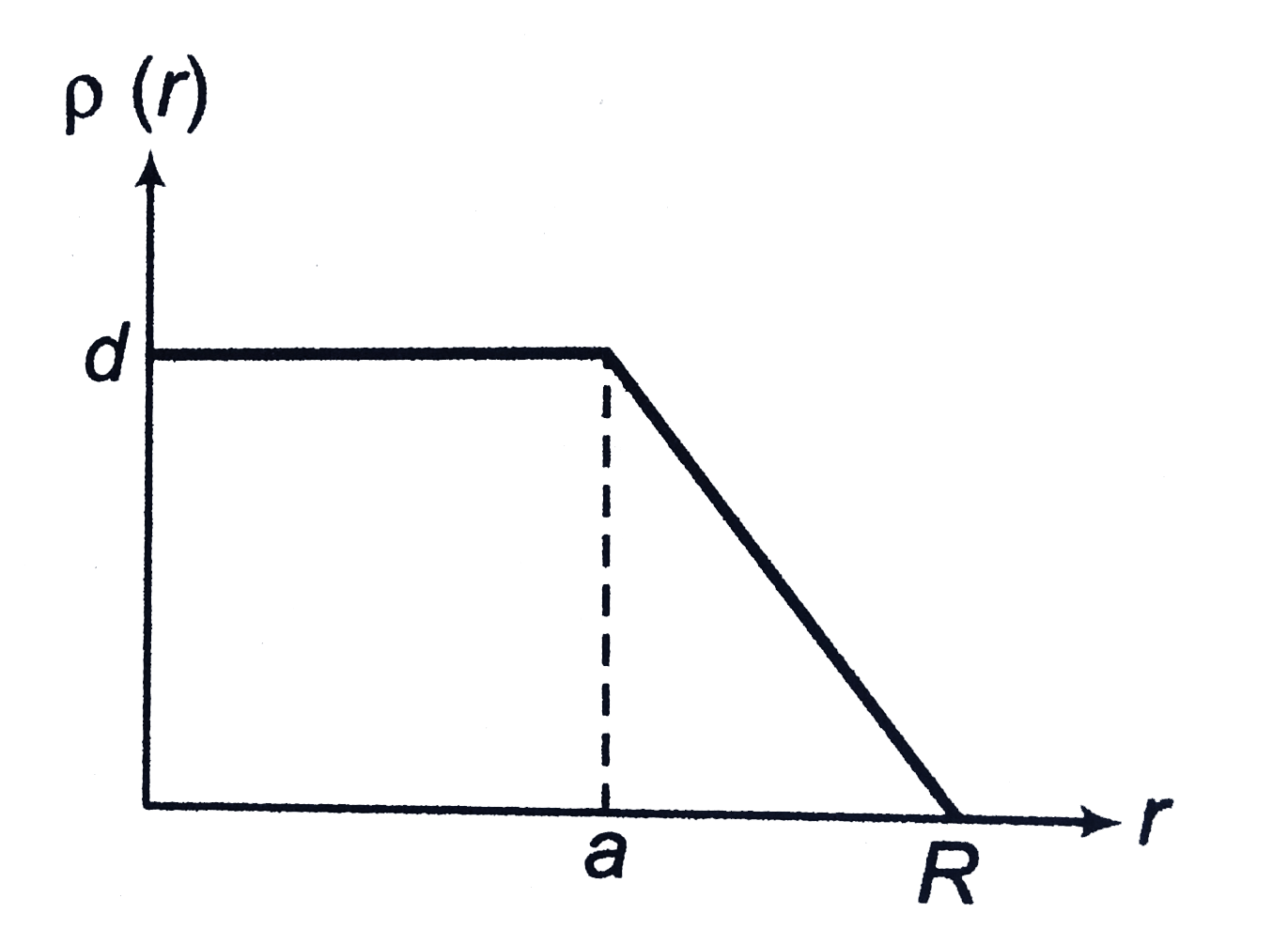
The electric field at r=R is View SolutionQuestion 61
The nuclear charge (Ze) is non uniformlly distribute with in a nucleus of radius r. The charge density ρ(r) (charge per unit volume) is dependent only on the radial distance r form the centre of the nucleus s shown in figure. The electric field is only along the radial direction.
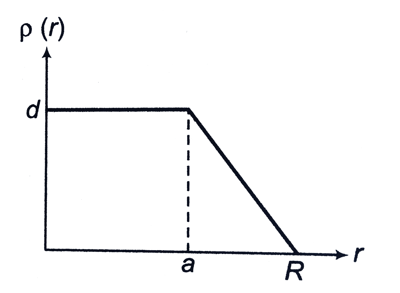
For a=0 the value of d (maximum value of ρ as shown in the figure) is
 View Solution
Question 62
The nuclear charge (Ze) is non uniformlly distribute with in a nucleus of radius r. The charge densilty ρ(r) (charge per unit volume) is dependent only on the radial distance r form the centre of the nucleus s shown in figure. The electric field is only along the radial direction.
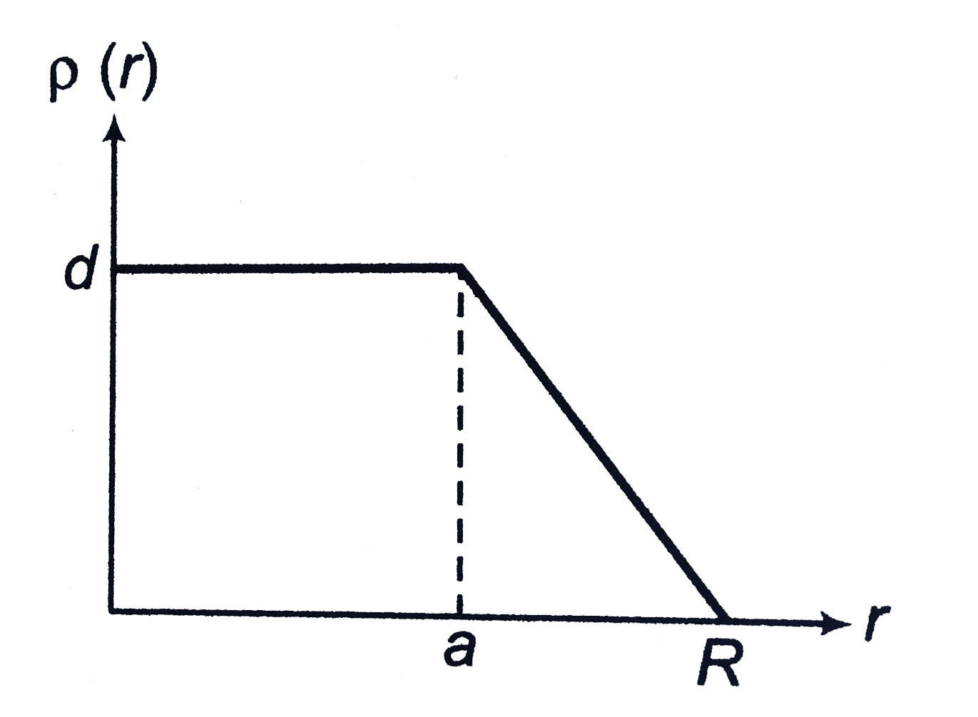
The electric field within the nucleus is generaly observed to be linearly dependent on r. This impliesView SolutionQuestion 63
A charge +Q is fixed at the origin of the co-ordinate system while a small electric dipole of dipolement →p pointing away from the charge along the x-axis is set free from a point far away from the origin.
(a) Calculate the K.E. of the dipole when it reaches to a point (d, 0).
(b) Calculate the force on the charge +Q at this moment. View SolutionQuestion 65
Ram ans Shyam purchased two electric tea kettles A and B of same size, same thickness, and same volume of 0.4L. They studied the specification of kettles as under
Ke≤A:
specific heat capacity =1680Jkg−1K−1
Mass = 200 g
Cost = Rs. 400
Kettle B:
Specific heat capacity = 2450Jkg−1K−1
Mass = 400 g
Cost = Rs. 400
When kettle A is switched on with constant potential source, the tea begins to boil in 6 min. When kettle B is switched on with the same source separately, then tea begins to boil in 8 min. The efficiengy of kettle is defined as
(Energy used for liquid heating)/(Total energy supplied)
They made discussion on specification and efficiency of kettles and subsequently prepared a list of questions to draw the conclusions. Some of them are as under (assume specific heat of tea liquid as 4200Jkg−1K−1 and density 1000kgm−3
Efficiency of kettle A is View SolutionQuestion 66
Ram ans Shyam purchased two electric tea kettles A and B of same size, same thickness, and same volume of 0.4L. They studied the specification of kettles as under
Ke≤A:
specific heat capacity =1680Jkg−1K−1
Mass = 200 g
Cost = Rs. 400
Kettle B:
Specific heat capacity = 2450Jkg−1K−1
Mass = 400 g
Cost = Rs. 400
When kettle A is switched on with constant potential source, the tea begins to boil in 6 min. When kettle B is switched on with the same source separately, then tea begins to boil in 8 min. The efficiengy of kettle is defined as
(Energy used for liquid heating)/(Total energy supplied)
They made discussion on specification and efficiency of kettles and subsequently prepared a list of questions to draw the conclusions. Some of them are as under (assume specific heat of tea liquid as 4200Jkg−1K−1 and density 1000kgm−3
Efficiency of kettle B is . View SolutionQuestion 67
Ram and Shyam purchased two electric tea kettles A and B of same size, same thickness, and same volume of 0.4L. They studied the specification of kettles as under
Ke≤A:
specific heat capacity =1680Jkg−1K−1
Mass = 200 g
Cost = Rs. 400
Kettle B:
Specific heat capacity = 2450Jkg−1K−1
Mass = 400 g
Cost = Rs. 400
When kettle A is switched on with constant potential source, the tea begins to boil in 6 min. When kettle B is switched on with the same source separately, then tea begins to boil in 8 min. The efficiengy of kettle is defined as
(Energy used for liquid heating)/(Total energy supplied)
They made discussion on specification and efficiency of kettles and subsequently prepared a list of questions to draw the conclusions. Some of them are as under (assume specific heat of tea liquid as 4200Jkg−1K−1 and density 1000kgm−3
Ratio of efficiency consumed charges for one time boiling of tea in kettle A to that in kettle B is View SolutionQuestion 68
Ram ans Shyam purchased two electric tea kettles A and B of same size, same thickness, and same volume of 0.4L. They studied the specification of kettles as under
Ke≤A:
specific heat capacity =1680Jkg−1K−1
Mass = 200 g
Cost = Rs. 400
Kettle B:
Specific heat capacity = 2450Jkg−1K−1
Mass = 400 g
Cost = Rs. 400
When kettle A is switched on with constant potential source, the tea begins to boil in 6 min. When kettle B is switched on with the same source separately, then tea begins to boil in 8 min. The efficiengy of kettle is defined as
(Energy used for liquid heating)/(Total energy supplied)
They made discussion on specification and efficiency of kettles and subsequently prepared a list of questions to draw the conclusions. Some of them are as under (assume specific heat of tea liquid as 4200Jkg−1K−1 and density 1000kgm−3
If resistances of coil of kettles A and B are RAandRB, respectively, then we can say View SolutionQuestion 69
Ram ans Shyam purchased two electric tea kettles A and B of same size, same thickness, and same volume of 0.4L. They studied the specification of kettles as under
Ke≤A:
specific heat capacity =1680Jkg−1K−1
Mass = 200 g
Cost = Rs. 400
Kettle B:
Specific heat capacity = 2450Jkg−1K−1
Mass = 400 g
Cost = Rs. 400
When kettle A is switched on with constant potential source, the tea begins to boil in 6 min. When kettle B is switched on with the same source separately, then tea begins to boil in 8 min. The efficiengy of kettle is defined as
(Energy used for liquid heating)/(Total energy supplied)
They made discussion on specification and efficiency of kettles and subsequently prepared a list of questions to draw the conclusions. Some of them are as under (assume specific heat of tea liquid as 4200Jkg−1K−1 and density 1000kgm−3
If both the kettles are joined with the same source in series one after the other, then boiling starts in kettle A and kettle B after View SolutionQuestion 70
Electric fuse is a protective device used in series with an electric circuit or an electric appliance to save it from damage due to overheating porduced by strong current in the circuit or application. Fuse wire is generally made from an alloy of lead and tin, which has hifh resistance and low melting point. It is connected in series in an electric installation. If a circuit gets accidentally short-circuited, a large current flows, then fuse wire melts away, which causes a break in the circuit. The power through fuse (F') is equal to heat energy lost per unit area per unit time (h) (neglecting heat loses from ends of the wire).
P=I2R=h×2πrl[R=ρlπr2]
where r and l are the length and radius of fuse wire, respectively.
A Battery is described by its emf (E) and internal resistance (r). Efficiency of battery (η) is defined as the ratio of the output to the input power.
η=OutputpowerInputpower×100%
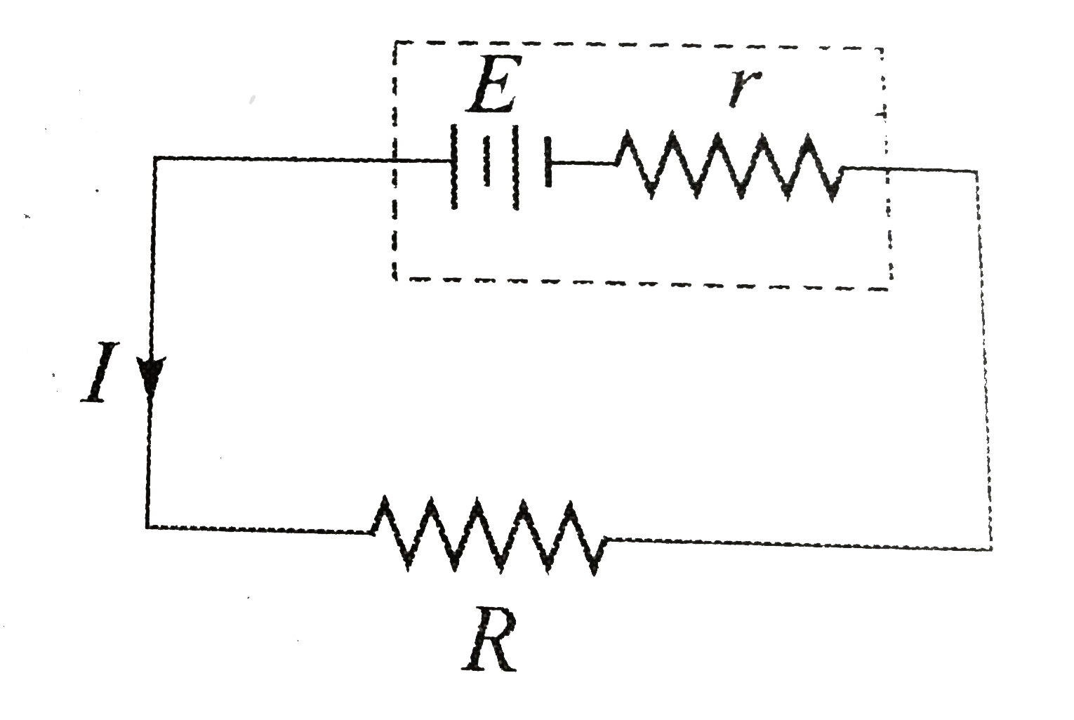
But I=E/(R+r), input power = EI.
Output power =EI−I2r, then.
η=(EI−I2rEI)×100=(1−IrE)×100
=[1−(ER+r)(rE)]×100=(RR+r)×100
We know that output power of a source is maximum when the external resistance is equal to internal resistance, i.e., R = r .
Two fuse wires of same potential , material have length ratio 1:2 and ratio of radius 4:1. Then respective ratio of their current rating will be View SolutionQuestion 71
Electric fuse is a protective device used in series with an electric circuit or an electric appliance to save it from damage due to overheating porduced by strong current in the circuit or application. Fuse wire is generally made from an alloy of lead and tin, which has hifh resistance and low melting point. It is connected in series in an electric installation. If a circuit gets accidentally short-circuited, a large current flows, then fuse wire melts away, which causes a break in the circuit. The power through fuse (F') is equal to heat energy lost per unit area per unit time (h) (neglecting heat loses from ends of the wire).
P=I2R=h×2πrl[R=ρlπr2]
where r and l are the length and radius of fuse wire, respectively.
A Battery is described by its emf (E) and internal resistance (r). Efficiency of battery (η) is defined as the ratio of the output to the input power.
η=OutputpowerInputpower×100%
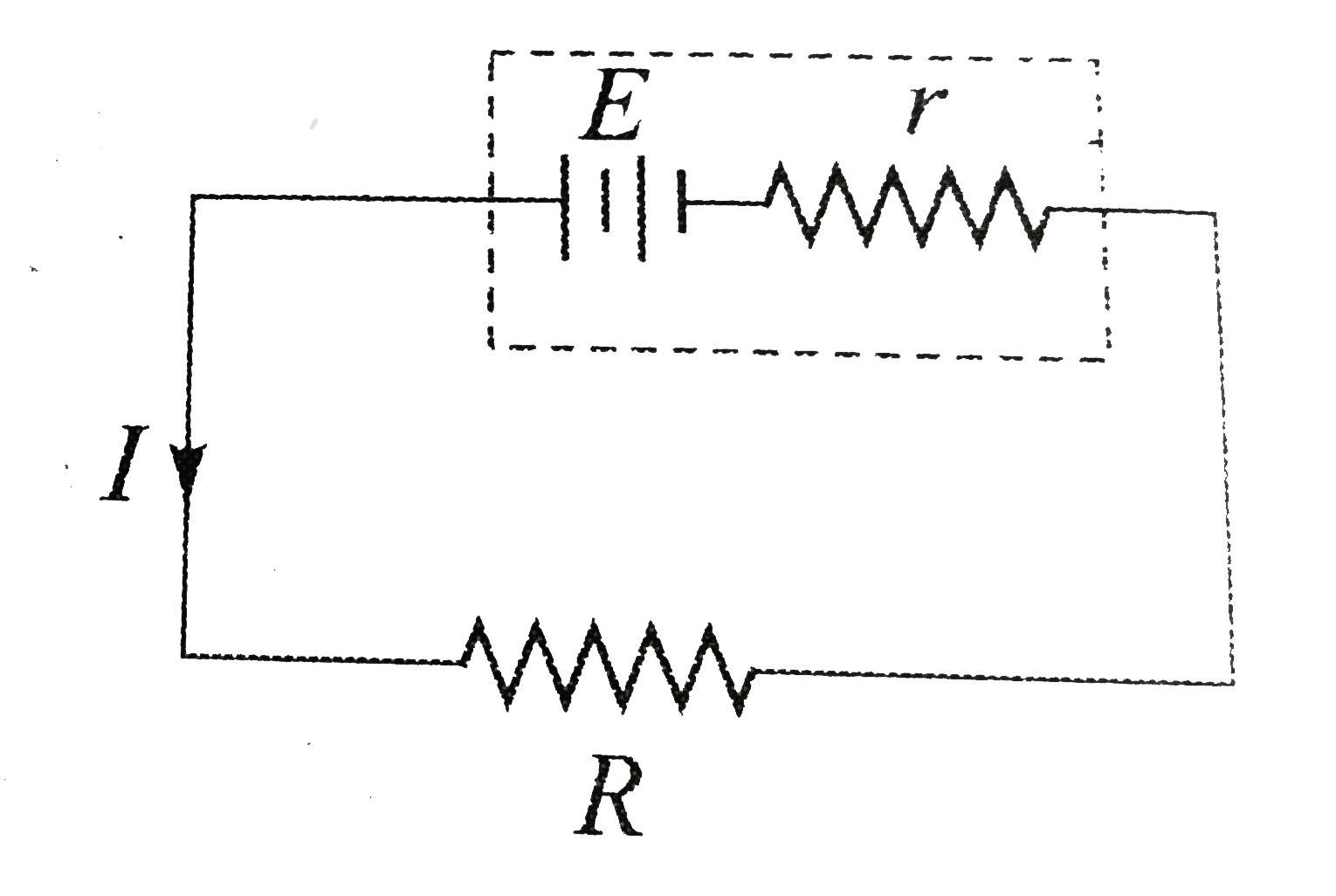
But I=E/(R+r), input power = EI.
Output power =EI−I2r, then.
η=(EI−I2rEI)×100=(1−IrE)×100
=[1−(ER+r)(rE)]×100=(RR+r)×100
We know that output power of a source is maximum when the external resistance is equal to internal resistance, i.e., R = r .
The maximum power rating of a 20.0Ω fuse wire is 2.0kW. This fuse wire can be connected safely to a DC source (negligible internal resistance) of View SolutionQuestion 72
Electric fuse is a protective device used in series with an electric circuit or an electric appliance to save it from damage due to overheating porduced by strong current in the circuit or application. Fuse wire is generally made from an alloy of lead and tin, which has hifh resistance and low melting point. It is connected in series in an electric installation. If a circuit gets accidentally short-circuited, a large current flows, then fuse wire melts away, which causes a break in the circuit. The power through fuse (F') is equal to heat energy lost per unit area per unit time (h) (neglecting heat loses from ends of the wire).
P=I2R=h×2πrl[R=ρlπr2]
where r and l are the length and radius of fuse wire, respectively.
A Battery is described by its emf (E) and internal resistance (r). Efficiency of battery (η) is defined as the ratio of the output to the input power.
η=OutputpowerInputpower×100%
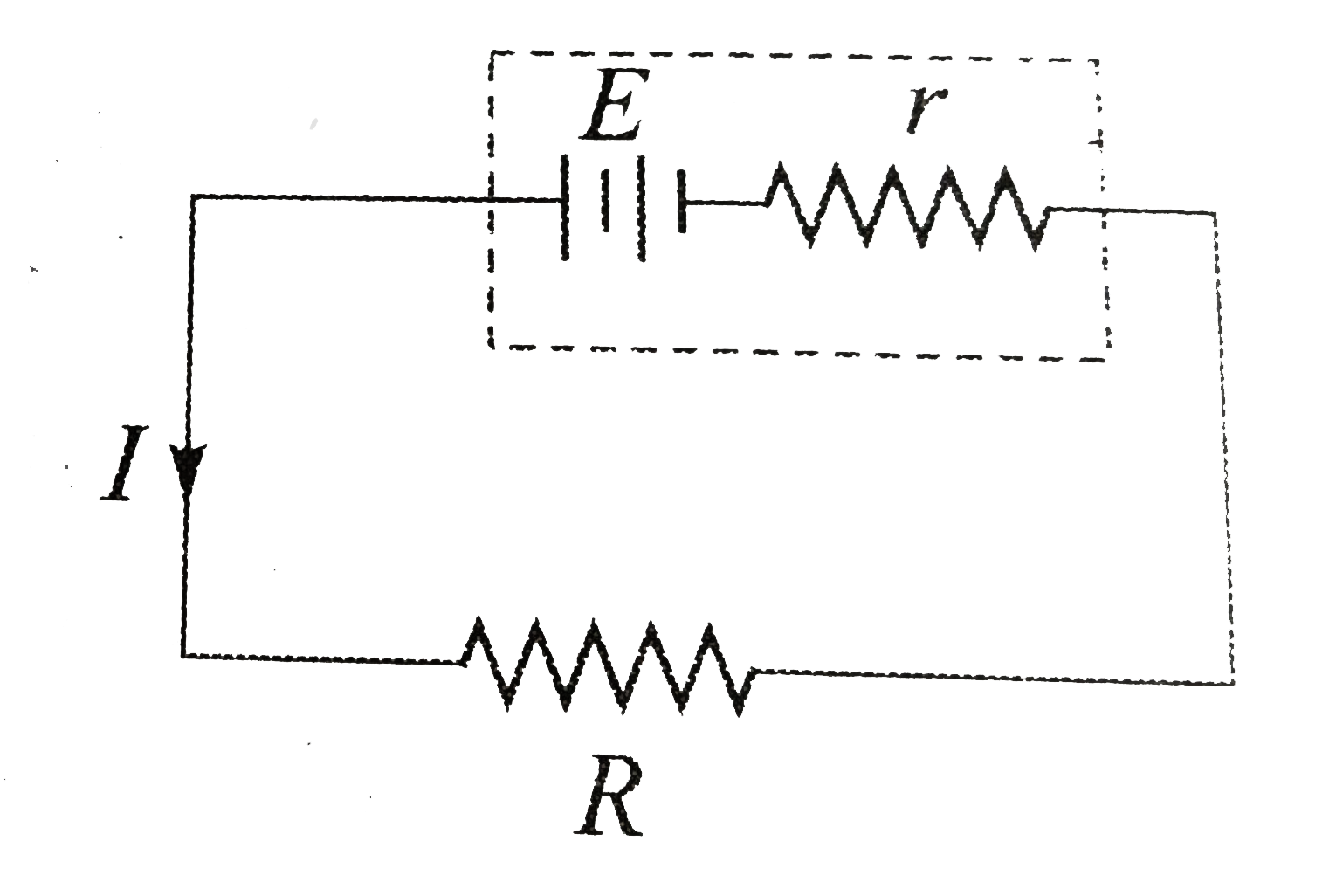
But I=E/(R+r), input power = EI.
Output power =EI−I2r, then.
η=(EI−I2rEI)×10(1−IrE)×100
=1−(ER+r)(rE)×100=(RR+r)×100
We know that output power of a source is maximum when the external resistance is equal to internal resistance, i.e., R = r .
Efficiency of a battery (nonideal) when delivering the maximum power is View SolutionQuestion 73
In the connection shown in the figure, initially the switch K is open and the capacitor is uncharged. Then the switch is closed, and the capacitor is charged up to the steady state and the switch is opened again. Determine the values indicated by the values indicated by the ammeter just after closing the switch
[GivenV0=30V,R1=10kΩ,R2=5kΩ]
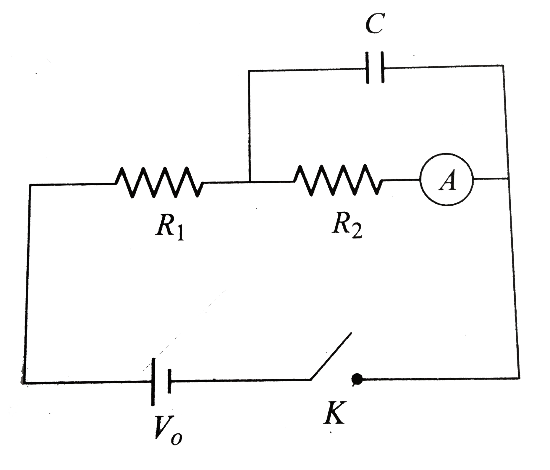 .
.
A long time after switch was closed.View SolutionQuestion 74
In the connecting shows in Fig. 6.68, intially swich K is open and the capacitor is uncharged. Then the switch is closed and the capacitor is changed up to the steady state and the switch is opened again. Determine the values indicated by thee ammeter.
(Given : V0=30V, R1=10kΩ,

A long time after the swich was closedView SolutionQuestion 75
In the connection shown in the figure, initially the switch K is open and the capacitor is uncharged. Then the switch is closed, and the capacitor is charged up to the steady state and the switch is opened again. Determine the values indicated by the values indicated by the ammeter just after closing the switch
[GivenV0=30V,R1=10kΩ,R2=5kΩ]
 .
.
A long time after switch was closed.View SolutionQuestion 76
The value of resistance of an unknown resistor is calculated using the formula R=V/I where V and I are the readings of the voltmeter and the ammeter, respectivley. Consider the circuits below. The internal resistances of the voltmeter and the ammeter (RVandRG,respectively) are finite and nonzero.
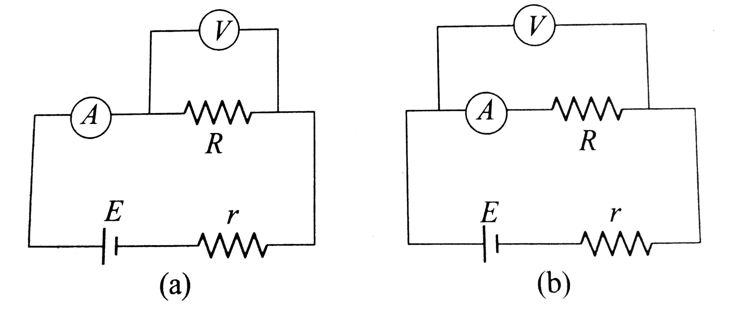 ,
,
Let RAandRB be the calculated values in the two cases A and B , respectively.
If the resistance of voltmeter is RV=1kΩ and the percentage error in the measurement of R (the value of R is nearly 10Ω)is View SolutionQuestion 77
The value of resistance of an unknown resistor is calculated using the formula R=V/I where V and I are the readings of the voltmeter and the ammeter, respectivley. Consider the circuits below. The internal resistances of the voltmeter and the ammeter (RVandRG,respectively) are finite and nonzero.
 ,
,
Let RAandRB be the calculated values in the two cases A and B , respectively.
If the resistance of voltmeter is RV=1kΩ and the percentage error in the measurement of R (the value of R is nearly 10Ω)is View SolutionQuestion 78
The value of resistance of an unknown resistor is calculated using the formula R=V/I where V and I are the readings of the voltmeter and the ammeter, respectivley. Consider the circuits below. The internal resistances of the voltmeter and the ammeter (RVandRG,respectively) are finite and nonzero.
 ,
,
Let RAandRB be the calculated values in the two cases A and B , respectively.
If the resistance of voltmeter is RV=1kΩ and the percentage error in the measurement of R (the value of R is nearly 10Ω)is View SolutionQuestion 79
In the circuit given in the figure, both batteries are ideal . Emf E1 of battery 1 has a fixed value, but emf E2 of battery 2 can be varied between 1.0Vand10.0V . The graph gives the currents through the two batteries as a function of E2 but are not marked as which plot corresponds to which battery. But for both plots, current is assumed to be negative when the direction of the current through the battery is opposite to the direction of that battery's emf (direction of emf is from negative to positive.)
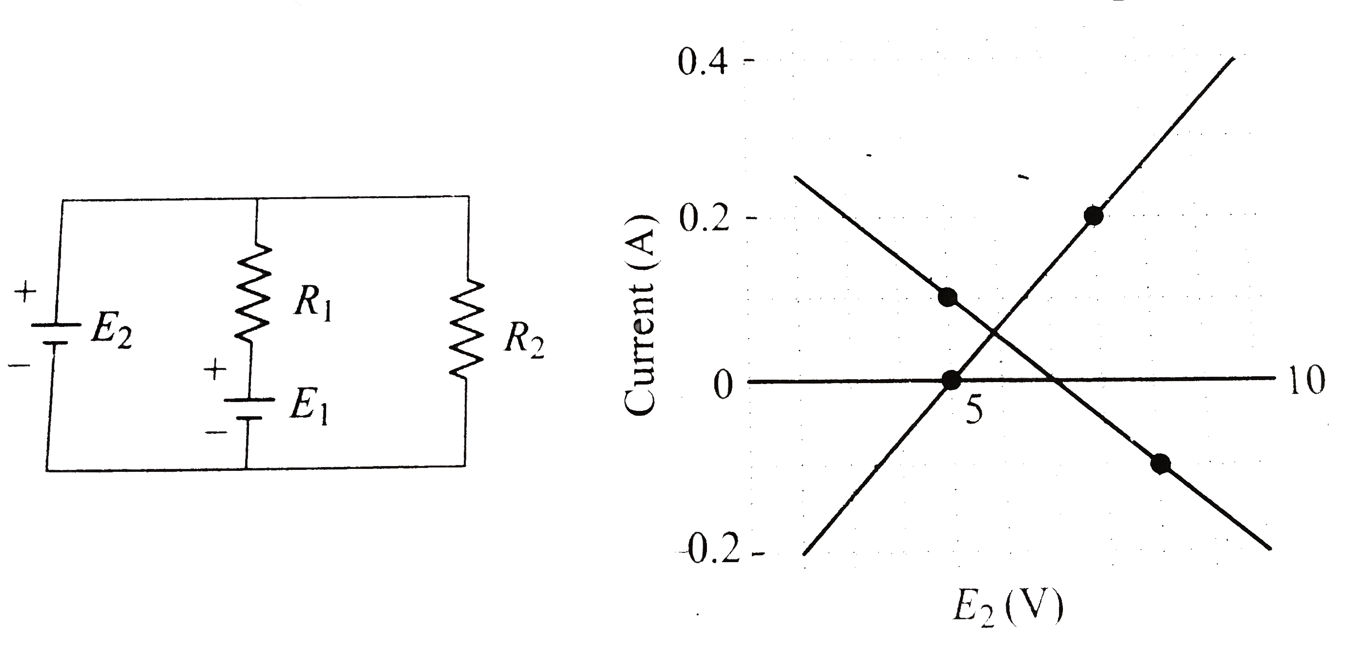
The value of emf E1 is View SolutionQuestion 80
In the circuit given in the figure, both batteries are ideal . Emf E1 of battery 1 has a fixed value, but emf E2 of battery 2 can be varied between 1.0Vand10.0V . The graph gives the currents through the two batteries as a function of E2 but are not marked as which plot corresponds to which battery. But for both plots, current is assumed to be negative when the direction of the current through the battery is opposite to the direction of that battery's emf (direction of emf is from negative to positive.)
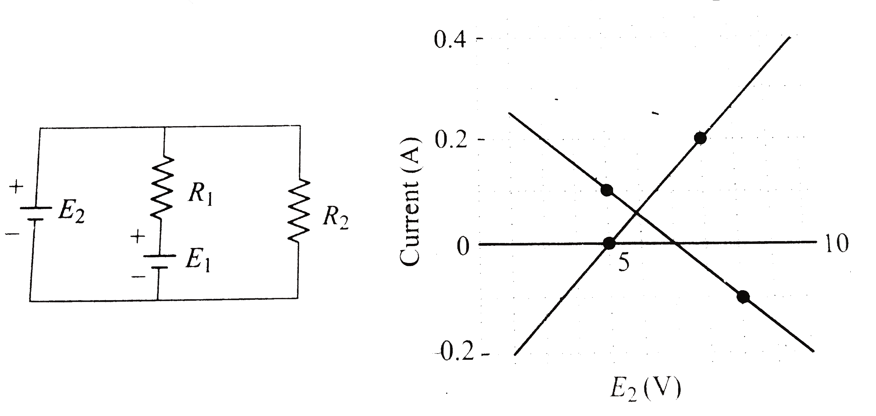 ,
,
The resistance R1 has value View SolutionQuestion 81
In the circuit given in the figure, both batteries are ideal . Emf E1 of battery 1 has a fixed value, but emf E2 of battery 2 can be varied between 1.0Vand10.0V . The graph gives the currents through the two batteries as a function of E2 but are not marked as which plot corresponds to which battery. But for both plots, current is assumed to be negative when the direction of the current through the battery is opposite to the direction of that battery's emf (direction of emf is from negative to positive.)
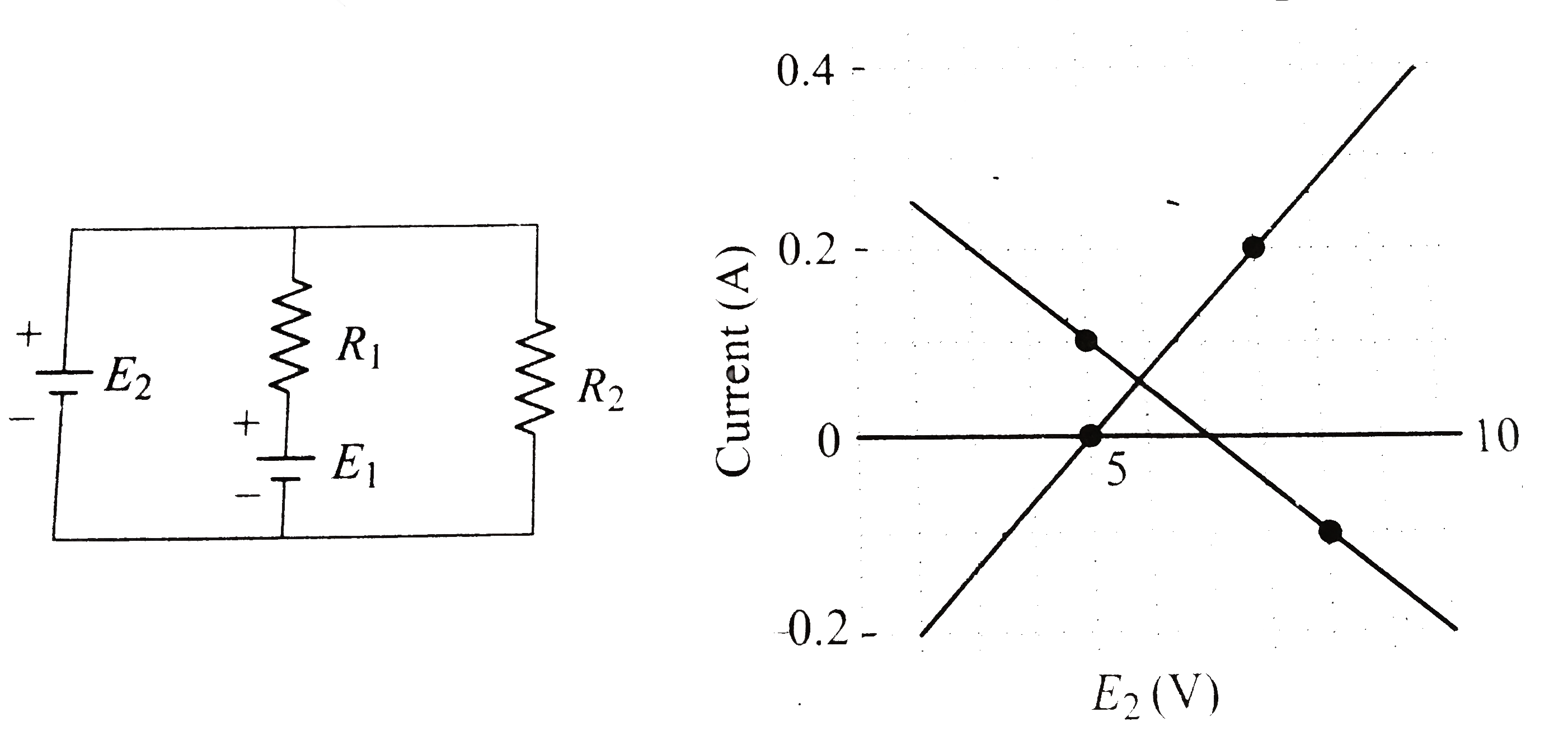 ,
,
The resistance R2 is equal to View SolutionQuestion 90
An ohm meter measures the resistance placed between its leads. This resistance reading is indicated by a galvanometer that operates on current. The ohm meter has an internal source of voltage to create the necessary current to operate the galvanometer and also has approproate resistor to allow just right amount of current through galvanometer. A simple ohm meter is shown here.
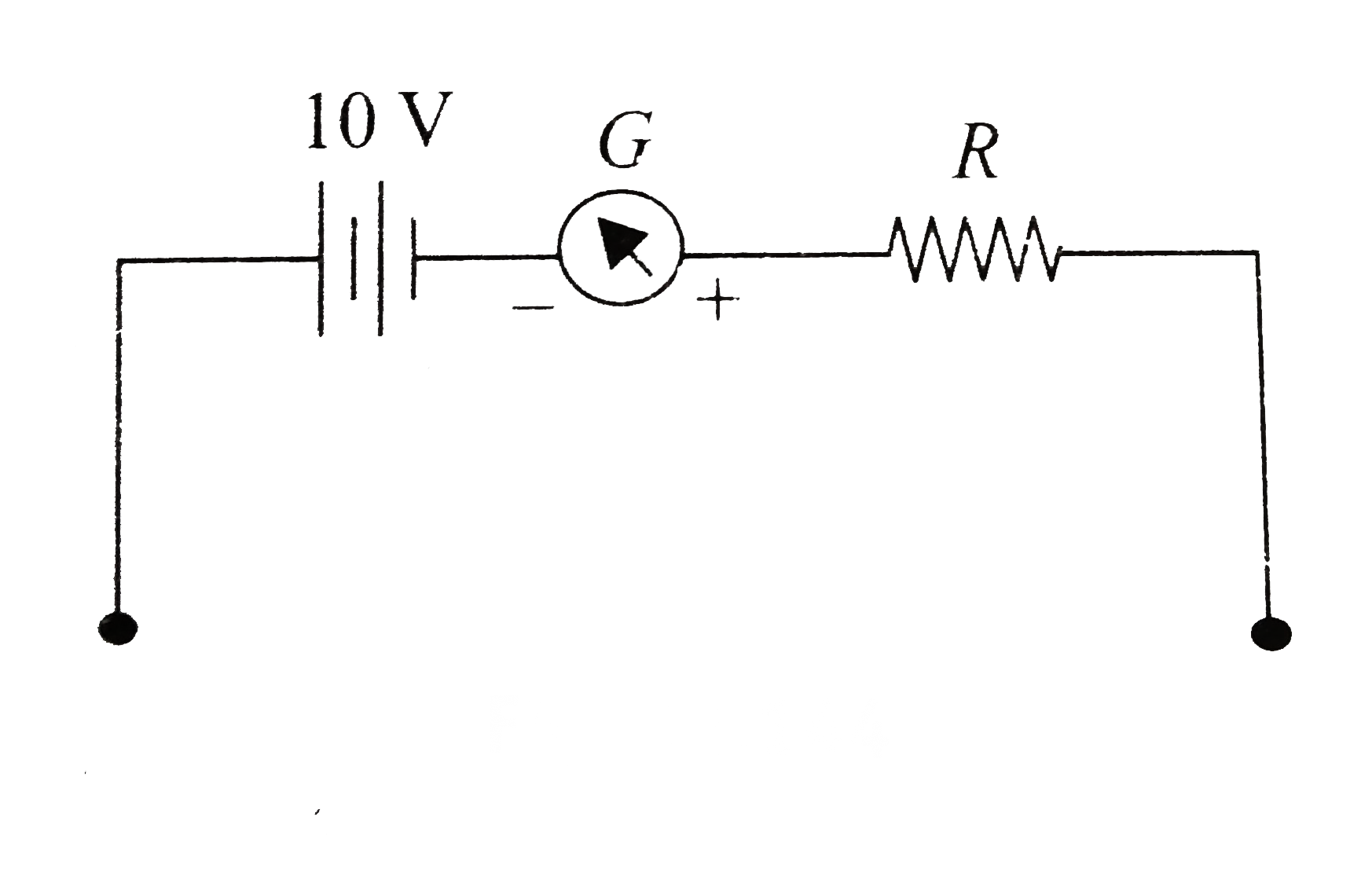
When there is an infinite resistance, there is zero current through galvanometer and it points in middle. If the test leads of this meter are directly shorted, (zero resistance) galvanometer will give full deflection.
Galvanometer specification
Resistance of galvanometer =100Ω
Fullscale current =0.5mA
Total number of division =40 .
View SolutionQuestion 91
An ohm meter measures the resistance placed between its leads. This resistance reading is indicated by a galvanometer that operates on current. The ohm meter has an internal source of voltage to create the necessary current to operate the galvanometer and also has approproate resistor to allow just right amount of current through galvanometer. A simple ohm meter is shown here.

When there is an infinite resistance, there is zero current through galvanometer and it points in middle. If the test leads of this meter are directly shorted, (zero resistance) galvanometer will give full deflection.
Galvanometer specification
Resistance of galvanometer =100Ω
Fullscale current =0.5mA
Total number of division =40 .
View SolutionQuestion 92
An ohm meter measures the resistance placed between its leads. This resistance reading is indicated by a galvanometer that operates on current. The ohm meter has an internal source of voltage to create the necessary current to operate the galvanometer and also has approproate resistor to allow just right amount of current through galvanometer. A simple ohm meter is shown here.

When there is an infinite resistance, there is zero current through galvanometer and it points in middle. If the test leads of this meter are directly shorted, (zero resistance) galvanometer will give full deflection.
Galvanometer specification
Resistance of galvanometer =100Ω
Fullscale current =0.5mA
Total number of division =40 .
if we want to measure 5 Omega Resistance than what is the position of needle View Solution


 ,
, 

 .
.