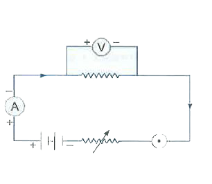
The following circuit diagram shows the experimental set-up for the study of dependence of current on potential difference. Which two circuit components are connected in series?

Ammeter and rheostat are connected in series.
This is because only one common point exists between ammeter, cell and rheostat.
Topper's Solved these Questions
- PRACTICAL BASED QUESTIONSBOOK - VK GLOBAL PUBLICATIONCHAPTER - PRACTICAL BASED QUESTIONSEXERCISE - Experiment 5
9 Videos
- PRACTICAL BASED QUESTIONSBOOK - VK GLOBAL PUBLICATIONCHAPTER - PRACTICAL BASED QUESTIONSEXERCISE - Experiment 6
4 Videos
- PRACTICAL BASED QUESTIONSBOOK - VK GLOBAL PUBLICATIONCHAPTER - PRACTICAL BASED QUESTIONSEXERCISE - Experiment 3
4 Videos
- PERIODIC CLASSIFICATION OF ELEMENTS BOOK - VK GLOBAL PUBLICATIONCHAPTER - PERIODIC CLASSIFICATION OF ELEMENTS EXERCISE - PROFICIENCY EXERCISE (LONG ANSWER QUESTIONS)
3 Videos
- VALUE-BASED QUESTIONSBOOK - VK GLOBAL PUBLICATIONCHAPTER - VALUE-BASED QUESTIONSEXERCISE - EXERCISE (CHAPTER-16) MANAGEMENT OF NATURAL RESOURCES
9 Videos
Similar Questions
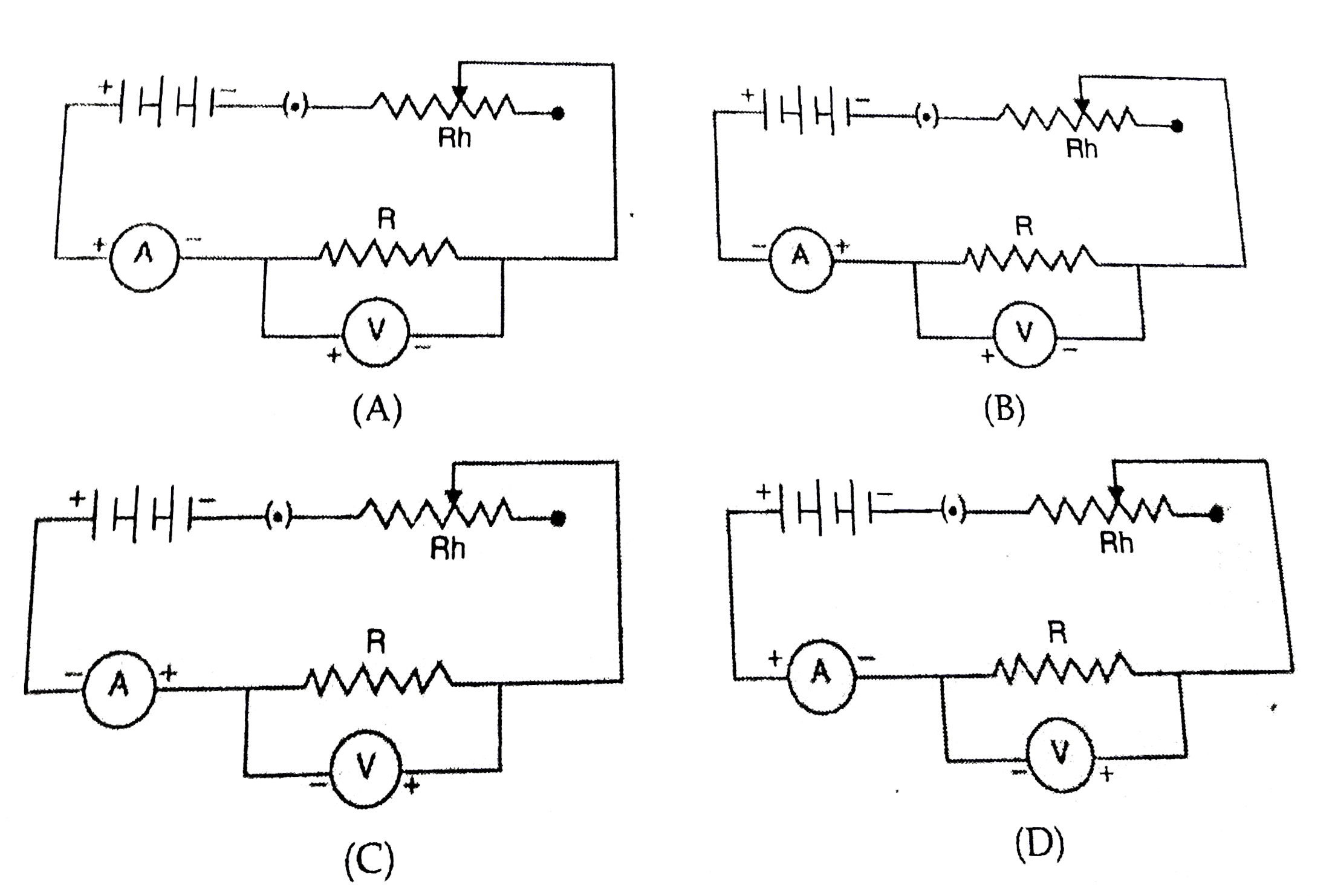
Which of the following is the correct set-up for studying the dependence of the current on the potential difference across a resistor and why?

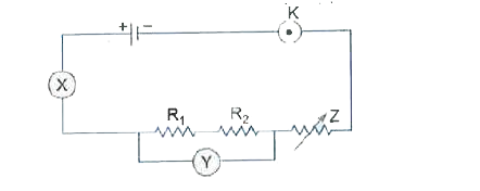
View SolutionThe given circuit diagram shows the experimental arrangement of different circuit components for determination of equivalent resistance of two resistors connected in series. Identify the components X, Y and Z shown in the circuit respectively.

View Solution
Knowledge Check
The following four circuits have been made for studying the dependence of current on the potential difference across a resistor.

The correct circuit is :AABBCCDDConsider the following circuits diagrams drawn by four students :

The correct circuit diagram for studying the dependence of current on the potential difference across a resistor is :AABBCCDDTo measure the current and potential difference of the resistances connected in series in a circuit, we will use
Aammeter and voltmeter both in series connectionBammeter and voltmeter both in parallel connectionCammeter in series and voltmeter in parallelDammeter in parallel and voltmeter in series
Draw a labelled circuit diagram to study the dependence of current (I) on the potential
difference (V) across a resistor.
View SolutionDraw a labelled circuit diagram to study the dependence of current (I) on the potential
difference (V) across a resistor.
View SolutionDraw a neat labelled circuit diagram of experimental arrangement for study of photoeletric effect.
View SolutionTo measure the current and potential difference of the resistances connected in series in a circuit, we will use
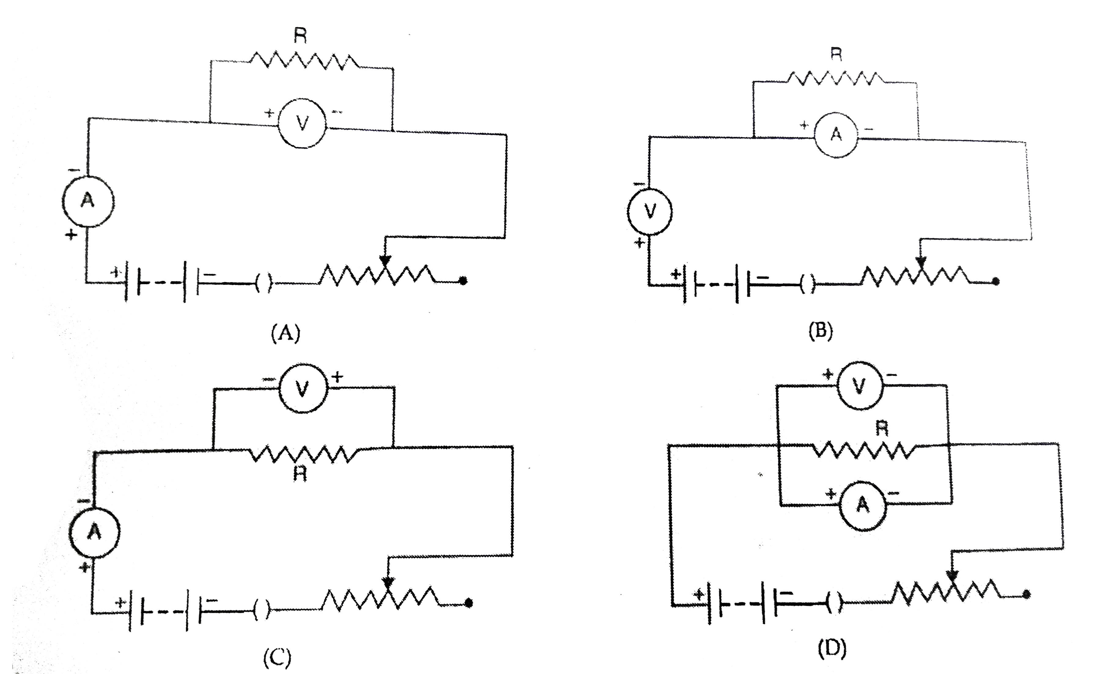
View SolutionWhich circuit diagram shows voltmeter V and ammeter A correctly positioned to measure the total potential difference of the circuit and the current through each resistor?
View Solution
