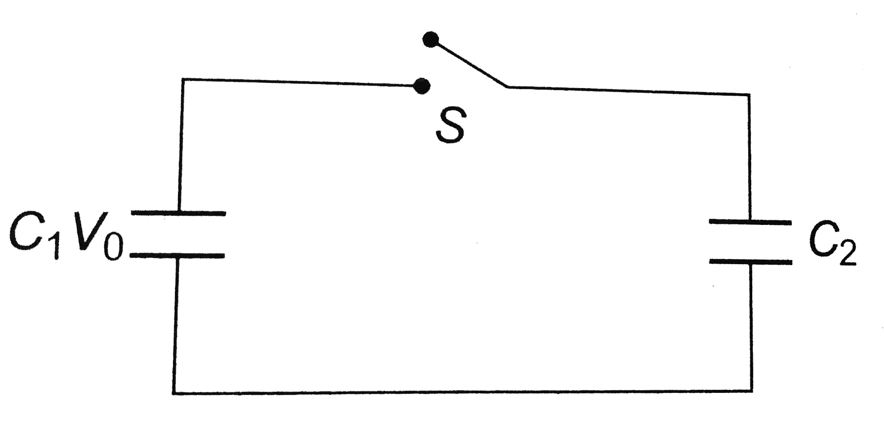
A capacitor of capacity C1=1μF is charged to a potential of 100 V. The charging battery is then removed and it is connected to another capacitor of capacity C2=2μF. One plate of C2 is earthed as shown in figure. The charges on C1andC2 in steady state will be

50μC,50μC
100μC,zero
1003μC,2003μC
zero,zer
The correct Answer is:B
Step by step video, text & image solution for A capacitor of capacity C_(1) = 1 muF is charged to a potential of 100 V. The charging battery is then removed and it is connected to another capacitor of capacity C_(2) = 2 muF. One plate of C_(2) is earthed as shown in figure. The charges on C_(1) and C_(2) in steady state will be by Physics experts to help you in doubts & scoring excellent marks in Class 11 exams.
Updated on:21/07/2023Topper's Solved these Questions
- ELECTROSTATICSBOOK - DC PANDEYCHAPTER - ELECTROSTATICSEXERCISE - Comprehension
36 Videos
- ELECTROSTATICSBOOK - DC PANDEYCHAPTER - ELECTROSTATICSEXERCISE - Matrix Matching
2 Videos
- ELECTROSTATICSBOOK - DC PANDEYCHAPTER - ELECTROSTATICSEXERCISE - Integer
17 Videos
- ELASTICITYBOOK - DC PANDEYCHAPTER - ELASTICITYEXERCISE - Medical entrances s gallery
21 Videos
- EXPERIMENTSBOOK - DC PANDEYCHAPTER - EXPERIMENTSEXERCISE - Subjective
15 Videos
Similar Questions
A capacitor of capacity 2μF is charged to 100V. What is the heat ( in mili joule ) generated when this capacitor is connected in parallel to n another capacitor of same capacity?
View SolutionA 2μF capacitor C1 is first charged to a potential difference of 10 V using a battery. Then the battery is removed and the capacitor is connected to an uncharged capacitor C2 of 8μF. The charge in C2 on equilibrium condition is _______μC. (Round off to the Nearest Integer)

View Solution
Knowledge Check
A capacitor C1 is charged to a p.d.V. The charging battery is then removed and the capacitor is connected to an uncharged capacitor C2. The final p.d. across the combination is
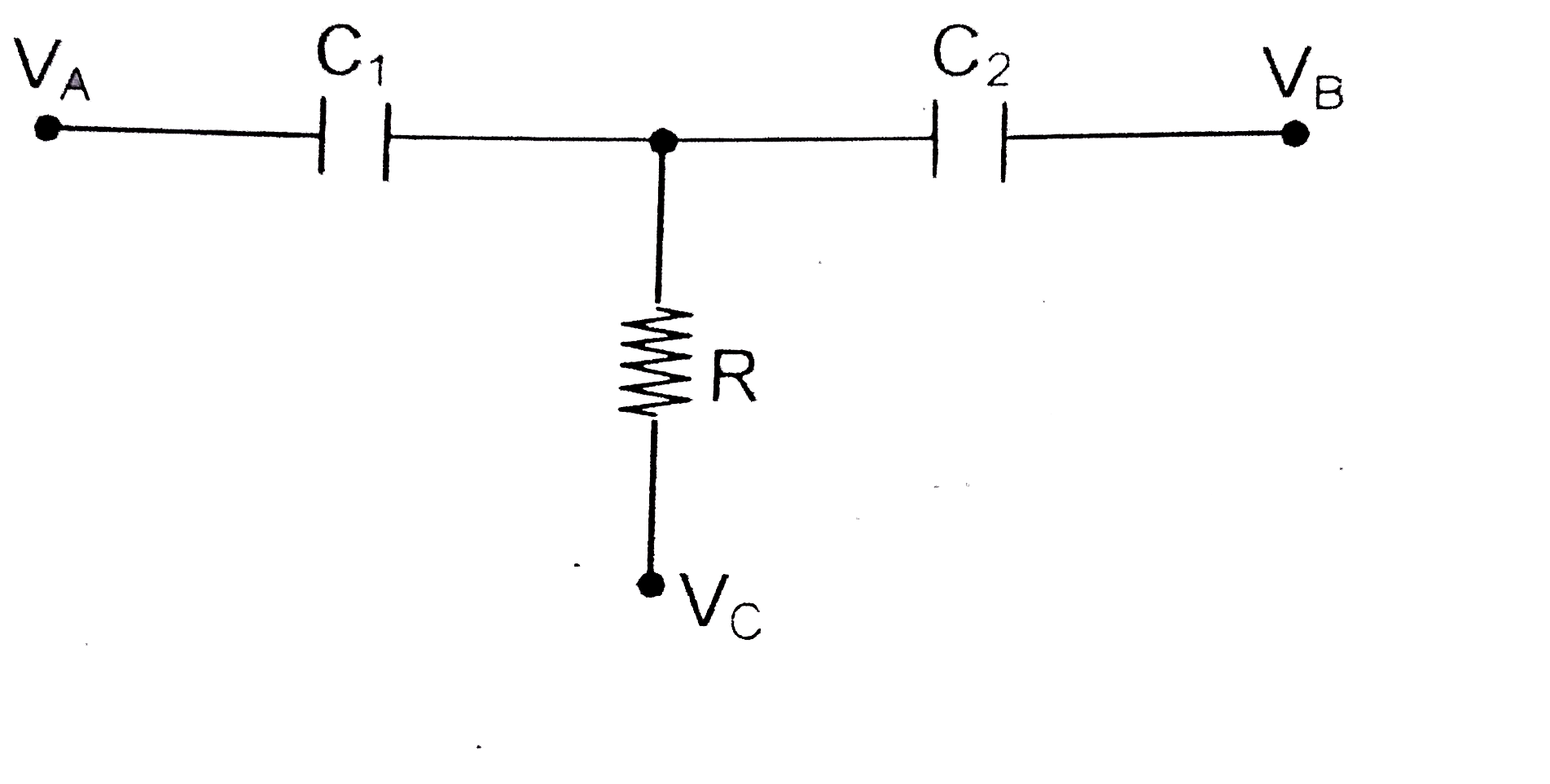
AVC1C1+C2BVC2C1+C2CVC1C2C1+C2DVC1+C2For given circuit charge on capacitor C, and C2 in steady state will be equal to
 AC1(VA−Vc),(Vc−VB) respectivelyBC1(VA−VB),C2(VA−VB) respectivelyC(C1+C2)(VA−VB) on each capacitorD(C1C2C1+C2)(VA−VB) on each capacitor
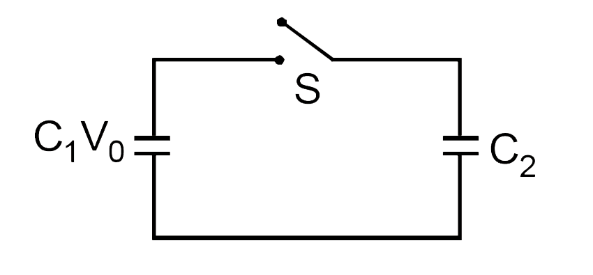
A capacitor of capacity C1 is charged to the potential of V0. On disconnecting with the battery, it is connected with a capacitor of capacity C2 as shown in the adjoining figure. The ratio of energies before and after the connection of switch S will be
 A(C1+C2)/C1BC1/(C1+C2)CC1C2DC1/C2
A capacitor of capacity 20microF is charged upto 50V and and disconnected from cell. Now this charged capacitor is connected to another capacitor of capacitance C If final common potential is 20V then find the capacitance C.
View SolutionA capacitor of capacitance 4μF is charged to a potential of 100 V. it is then disconnected from the battery and connected in parallel with another capacitor C2. If their common potential is 40 volts, then the value of C2 is
View SolutionA capacitor or capacitance C1 is charge to a potential V and then connected in parallel to an uncharged capacitor of capacitance C2. The fianl potential difference across each capacitor will be
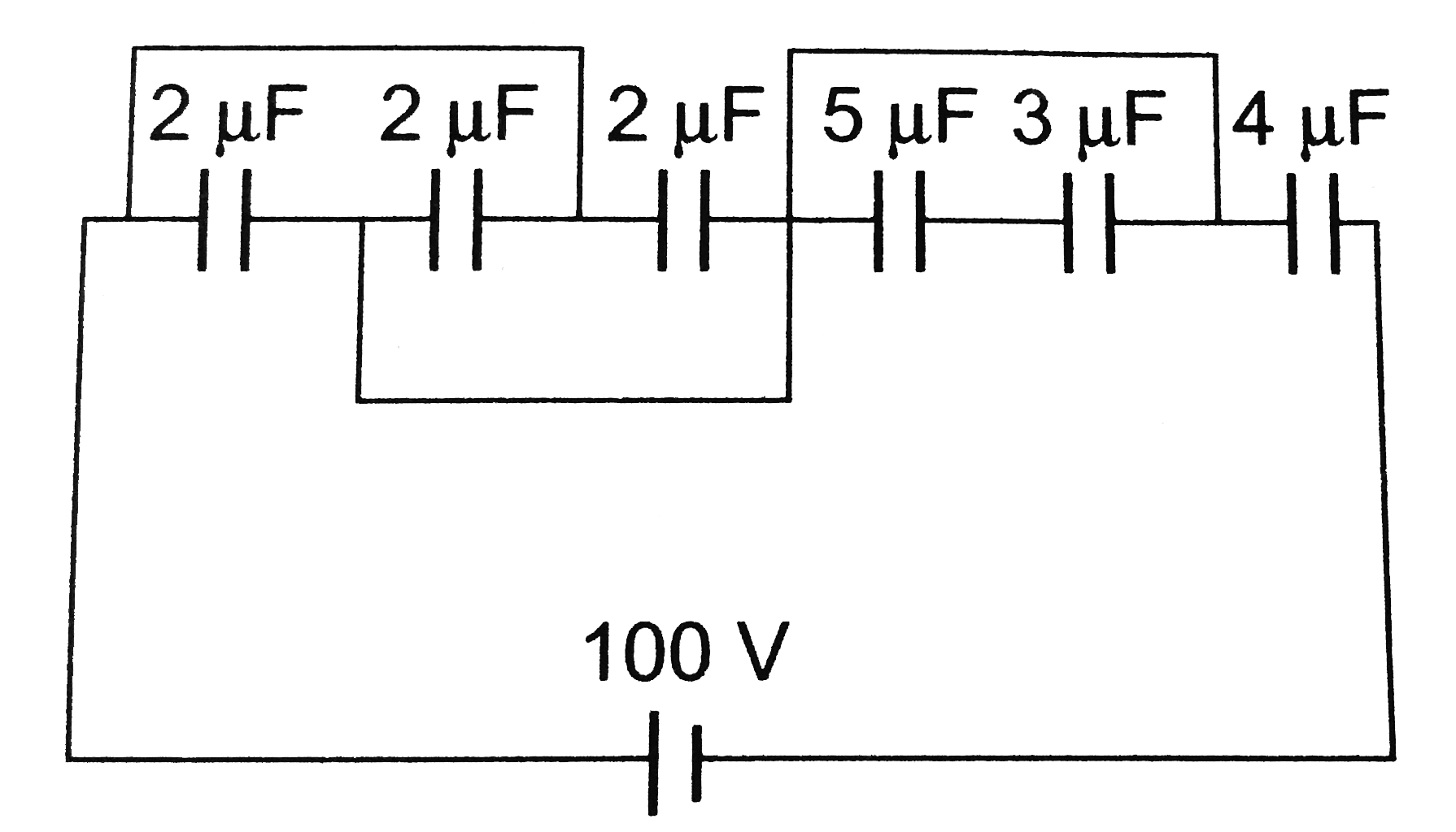
View SolutionIn the circuit shown in figure charge stored in the capacitor of capacity 5μF is

View SolutionA capacitor of capacity C1 is charged to the potential of V0. On disconnecting with the battery, it is connected with a capacity C2 as shown in the adjoining figure. The ratio of energies before and after the connection of switch S will be

View Solution
