A circuit is construnted using two torch bulbs and a cell, as shown in the given figure at the left. The figure at the right shows four arrows whose tips show their respective directions. These arrows have to be placed on each wire segments RS, RV, ST and TV respectively, according to the directions of current.

The given arrows that can be placed on wire segments RV, VT, ST, and RS are respectively


Step by step video & image solution for A circuit is construnted using two torch bulbs and a cell, as shown in the given figure at the left. The figure at the right shows four arrows whose tips show their respective directions. These arrows have to be placed on each wire segments RS, RV, ST and TV respectively, according to the directions of current. The given arrows that can be placed on wire segments RV, VT, ST, and RS are respectively by Physics experts to help you in doubts & scoring excellent marks in Class 6 exams.
Updated on:21/07/2023Topper's Solved these Questions
- ELECTRICITY BOOK - BEIITIANSCHAPTER - ELECTRICITY EXERCISE - IIT JEE Worksheet I. Single Correct Answer Type
12 Videos
- ELECTRICITY BOOK - BEIITIANSCHAPTER - ELECTRICITY EXERCISE - IIT JEE Worksheet II. Multiple Correct Answer Type
3 Videos
- ELECTRICITY BOOK - BEIITIANSCHAPTER - ELECTRICITY EXERCISE - Summative Worksheet
11 Videos
- ENERGY AND WORK BOOK - BEIITIANSCHAPTER - ENERGY AND WORK EXERCISE - IIT JEE WORKSHEET
34 Videos
Similar Questions
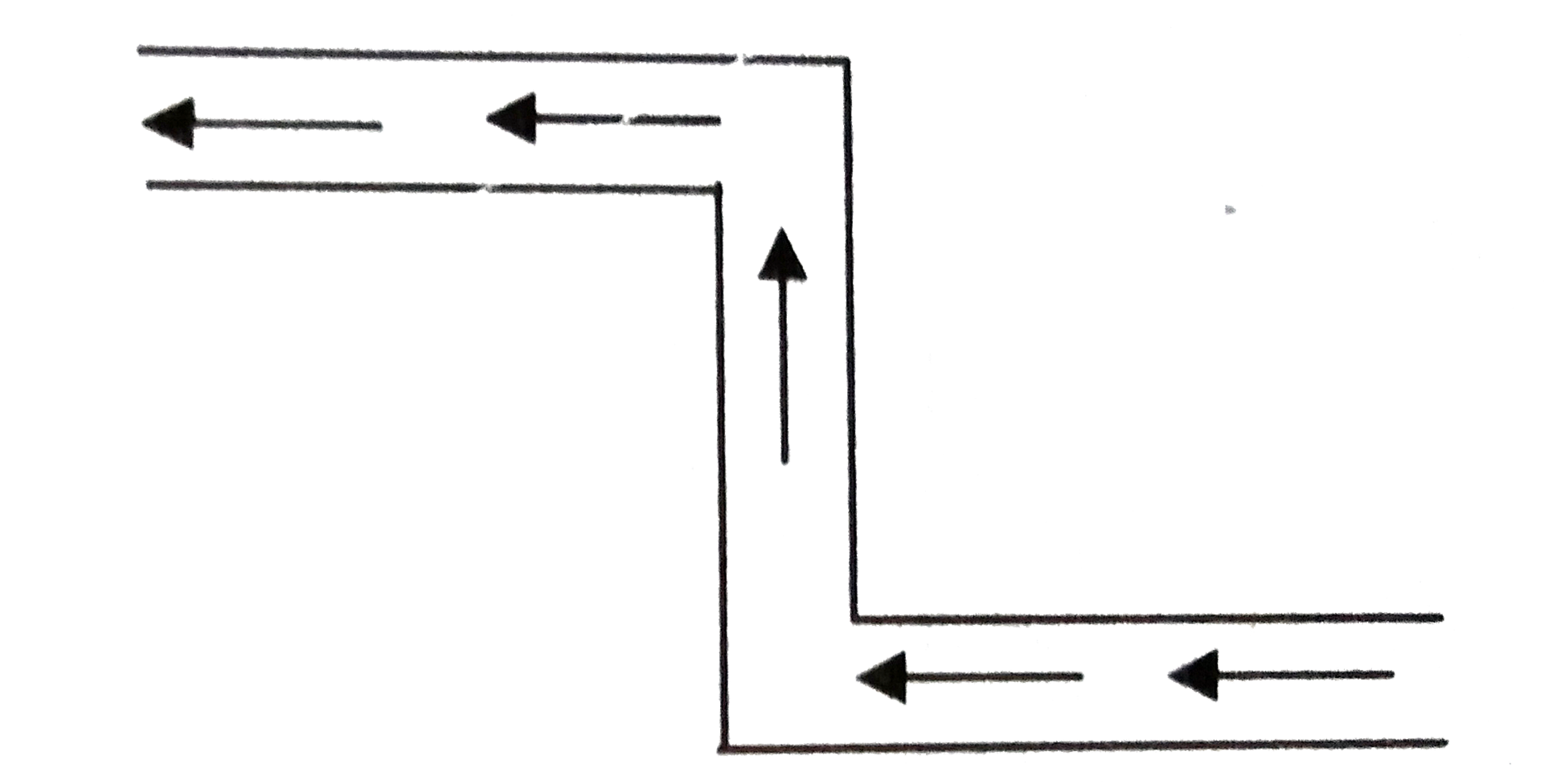
The figure bwlow indicates flow of water through a tube of uniform cross-section with a constant speed in the direction as shown by the arrows. On the tube, water exerts

View SolutionA bar magnet is moved in the direction indicated by the arrow between two coil PQ and CD. Predict the directions of induced current in each coil.

View Solution
Knowledge Check
The arrow keys can be used to ...
Adelete textBmove the cursor in the text that has already been enteredCsave the documentDmove the cursor while deleting textIn transistor symbols, the arrows shows shows the direction of-
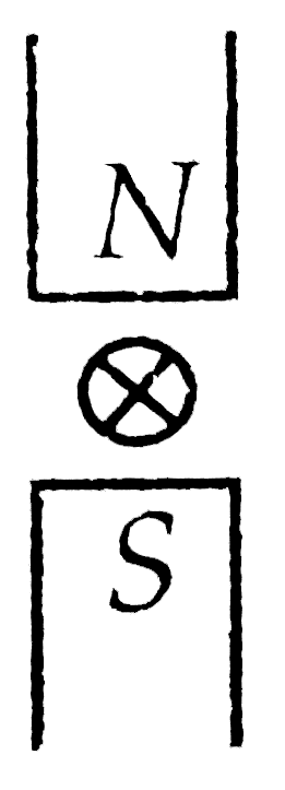
Acurrent in the emitterBelectron current in the emitterCholes current in the emitterDNone of theseA wire is placed between the poles of two fixed bar magnets as shown in the figure. A small current in the wire is into the plane of the paper. The direction of the magnetic force on the wire is
 A↑B↓C→D←
There are two wires ab and cd in a vertical plane as shown in figure. Direction of current in wire a is rightwards. Choose the correct options.

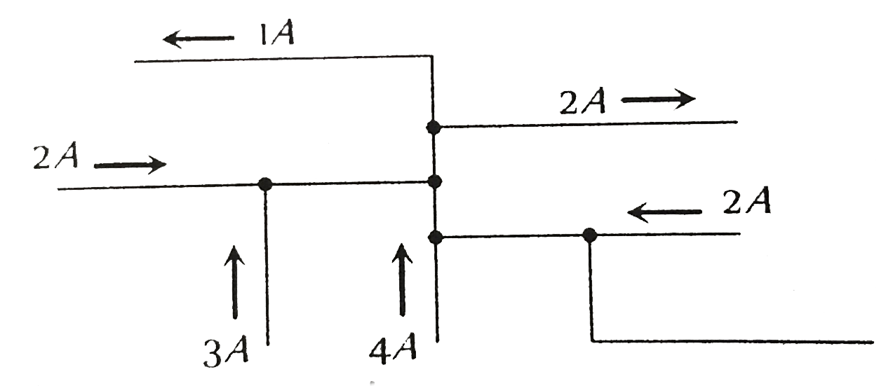
View SolutionThe figure here shows a portion of a circuit. What are the magnitude and direction of the current i in the lower right-hand wire

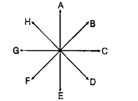
View SolutionIn the following diagram, which arrow shows the South-East direction?

View SolutionA wire is placed between the poles of twofixed bar magnets as shown in the figure. A small current in the wire is into the plane of the paper. The direction of the magnetic force on the wire is

View SolutionThe arrow head on the transistor symbol always points in the direction of
View Solution
