(a) Complete the circuit given in Fig. 1 by inserting between the terminals A and C, an ammeter. (b) In the diagram mark the polarity at the terminals of ammeter and indicate clearly the direction of flow of current in the circuit, when the circuit is complete. (c) Name and state the purpose of Rh in the circuit.

Step by step video & image solution for (a) Complete the circuit given in Fig. 1 by inserting between the terminals A and C, an ammeter. (b) In the diagram mark the polarity at the terminals of ammeter and indicate clearly the direction of flow of current in the circuit, when the circuit is complete. (c) Name and state the purpose of Rh in the circuit. by Physics experts to help you in doubts & scoring excellent marks in Class 9 exams.
Updated on:21/07/2023Topper's Solved these Questions
- CURRENT ELECTRICITYBOOK - ICSECHAPTER - CURRENT ELECTRICITYEXERCISE - Exercise-9(A)Multiple choice
3 Videos
- CURRENT ELECTRICITYBOOK - ICSECHAPTER - CURRENT ELECTRICITYEXERCISE - Exercise-9(A)Numericals
3 Videos
- CURRENT ELECTRICITYBOOK - ICSECHAPTER - CURRENT ELECTRICITYEXERCISE - Exercise-9(C ) Multiple choice
2 Videos
- ELECTRICITY AND MAGNETISM BOOK - ICSECHAPTER - ELECTRICITY AND MAGNETISM EXERCISE - TOPIC 2 Magnetism (4 Marks Questions )
6 Videos
Similar Questions
In the circuit Fig the final current through 30Ω resistance when circuit is completed is
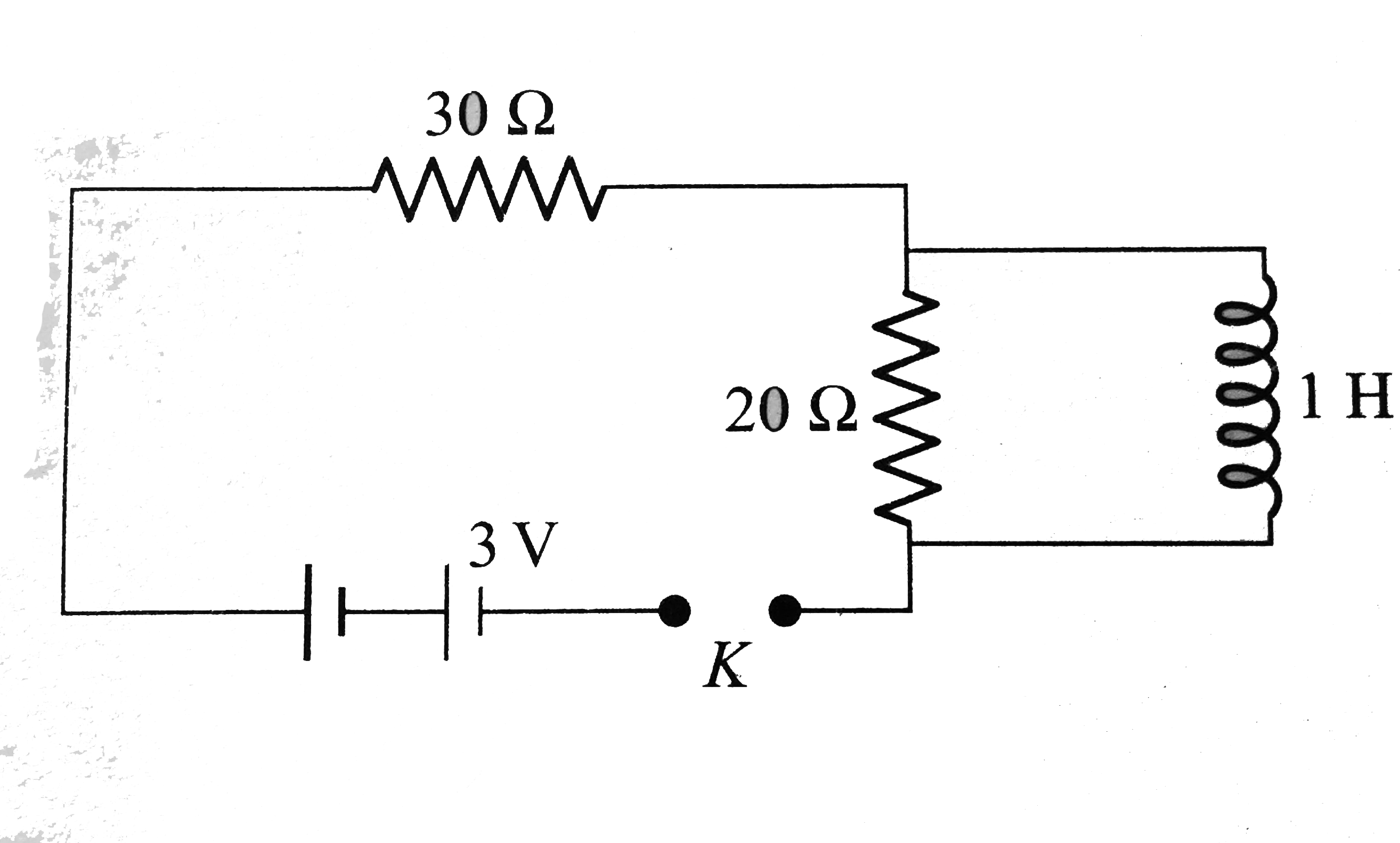
View SolutionThe time constant for LR circuit between the terminals a and b as shown in diagram is
View SolutionDraw a circuit diagram for a bulb connected to a cell with a switch. Mark arrows in the diagram to indicate the direction of flow of current.
View SolutionThe diagram given below (Fig.) shows a bulb connected with a cell having terminals A and B. Mark the direction of current in the bulb.
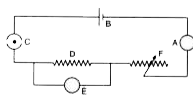
View SolutionIn the electric circuit shown in Fig., label the parts A, B, C, D, E, and E
State the function of each part. Show in the diagram the direction of flow of current.
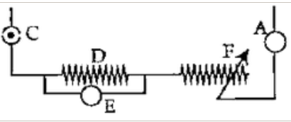
View SolutionIn the electric circuit shown in Fig. 1, label the parts A, B, C, D, E, and F State the function of each part. Show in the diagram the direction of flow of current.
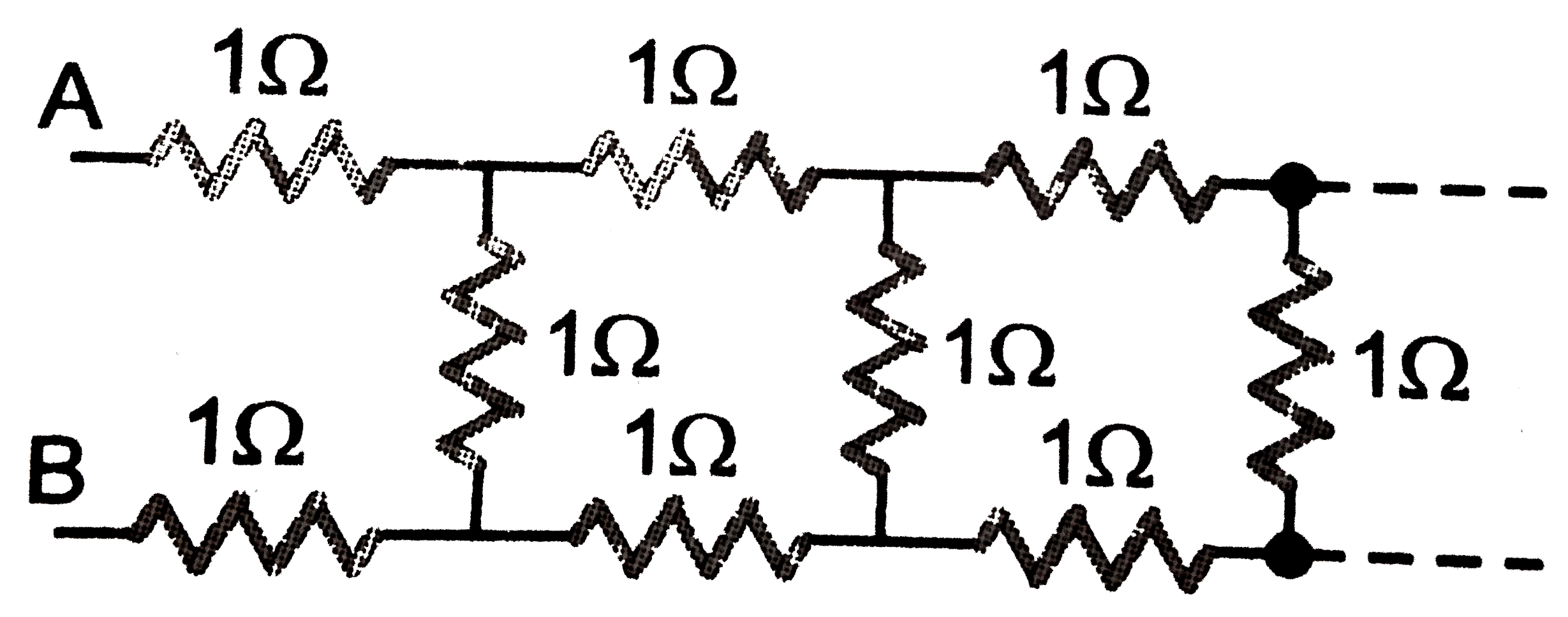
View SolutionThe resistance between the terminal point A and B of the given infinitely long circuit will be
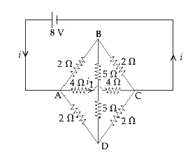
View SolutionThe value of current i1 flowing from A to C in the circuit diagram is :
View SolutionThe diagram shows a coil wound around a U shape soft iron bar AB.
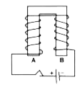
What will be the polarities at A and B if the direction of current is reversed in the circuit ?
View SolutionA current of 10A flows around a closed path in a circuit which is in the horizontal plane as shown in the figure. The circuit consists oi eight alternating arcs of radii r1=0.08m and r2=0.12m. Each subtends the same angle at the centre.
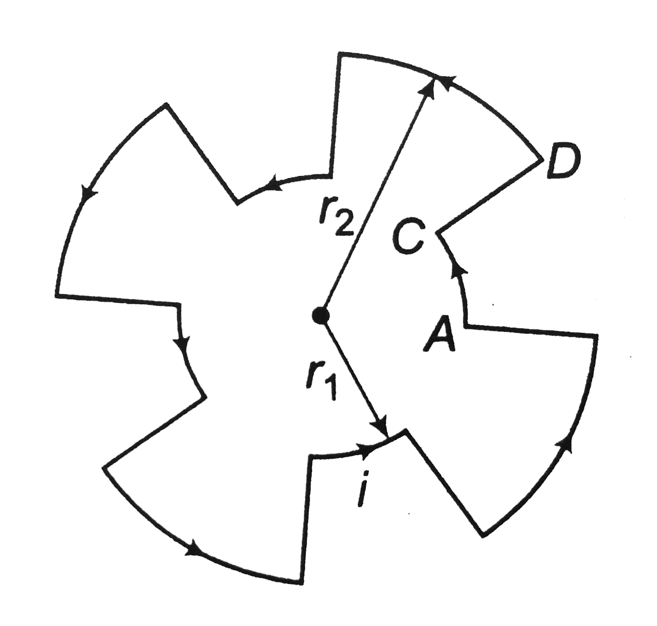
a. Find the magnetic field produced by this circuit at the centre.
b. An infinitely long straight wire carrying as current of 10A is passing through the centre of the above circuit vertically with the direction of the current being into the pane of the circuit. what is the force acting on the wire at the centre due to the current in the circuit? What is the force acting on the arc AC and the straight segment CD due to the current at the centre?
View Solution
