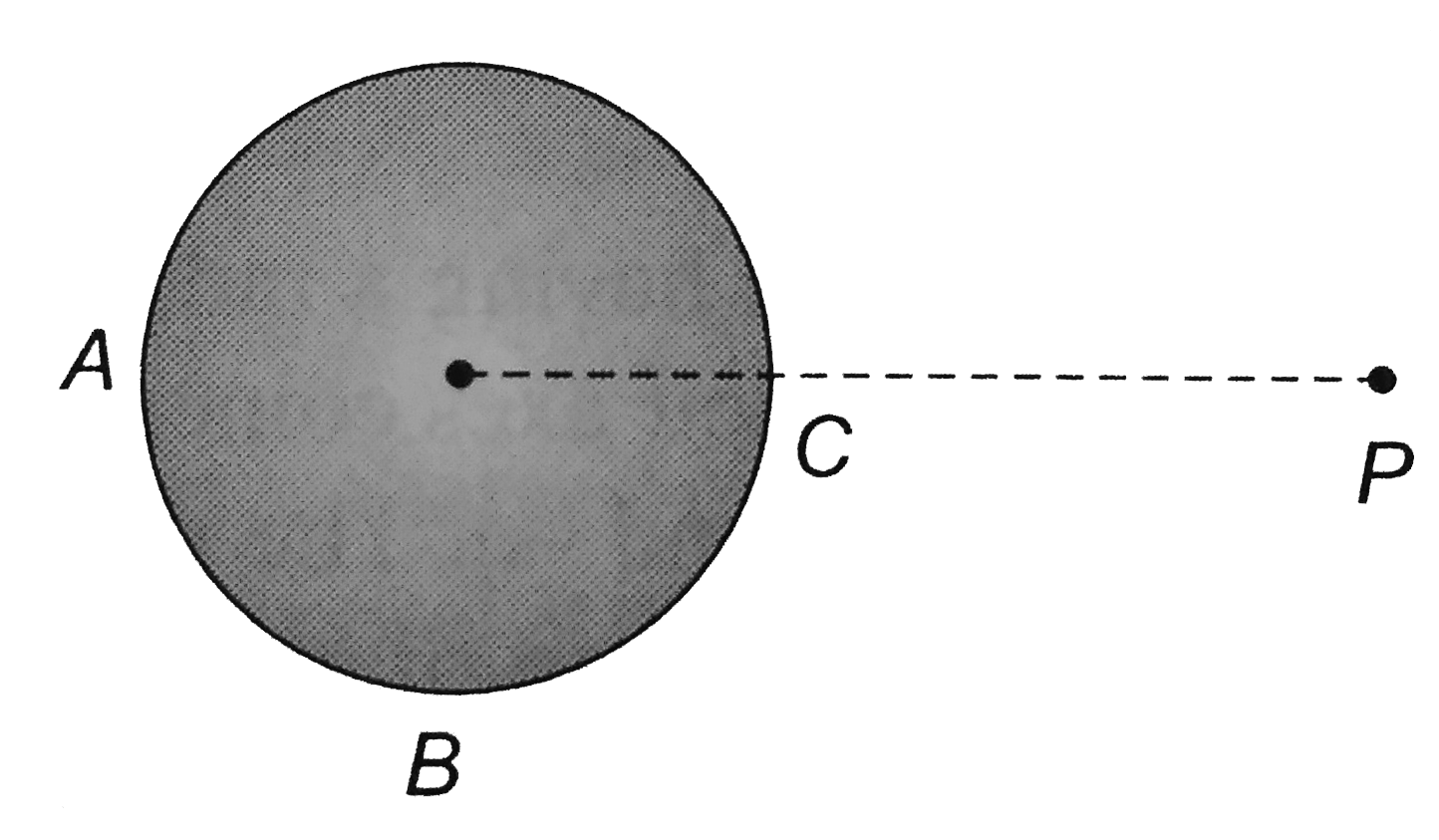
A hollow conducting sphere is placed in an electric field produced by a point charge placed at P as shown in figure.
Let VA,VB,VC be the potentials at points A,BandC respectively. Then
VC>VB
VB>VC
VA>VB
VA=VC
Step by step video & image solution for A hollow conducting sphere is placed in an electric field produced by a point charge placed at P as shown in figure. Let V_(A), V_(B), V_(C ) be the potentials at points A, B and C respectively. Then by Physics experts to help you in doubts & scoring excellent marks in Class 12 exams.
Updated on:21/07/2023Topper's Solved these Questions
- ELECTROSTATICS BOOK - ERRORLESS CHAPTER - ELECTROSTATICS EXERCISE - Ordinary Thinking Objective Questions (Electric Dipole)
38 Videos
- ELECTROSTATICS BOOK - ERRORLESS CHAPTER - ELECTROSTATICS EXERCISE - Ordinary Thinking Objective Questions (Electric Flux and Gauss.s Law)
28 Videos
- ELECTROSTATICS BOOK - ERRORLESS CHAPTER - ELECTROSTATICS EXERCISE - Ordinary Thinking Objective Questions (Electric Flux and Gauss.s Law)
28 Videos
- ELECTRONICSBOOK - ERRORLESS CHAPTER - ELECTRONICSEXERCISE - Selv Evaluation Test
23 Videos
- HEATING AND CHEMICAL EFFECT OF CURRENTBOOK - ERRORLESS CHAPTER - HEATING AND CHEMICAL EFFECT OF CURRENTEXERCISE - Self Evaluation Test
14 Videos
Similar Questions
The electric field and the electric potential at a point are E and V respectively.
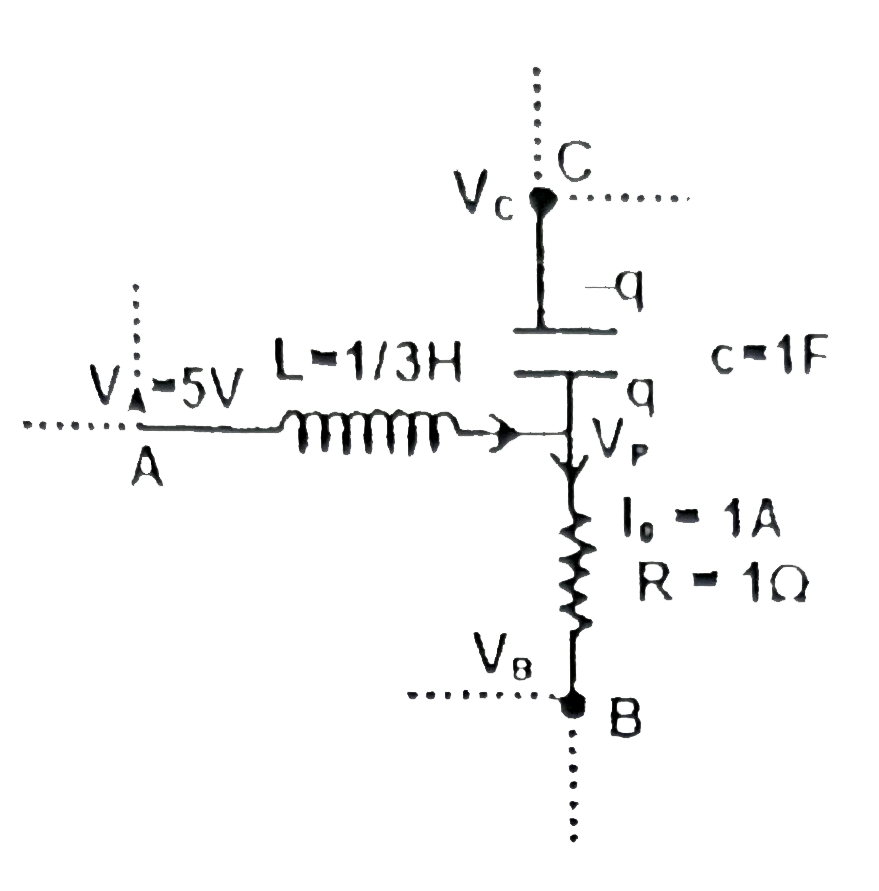
View SolutionGiven figure is the part of some circuit. Charge on the capacitor in the circuit is given by q=3(3−e−1), (coulomb) where t is time in seconds.
Let VA, VB and VC be the potentials of points A, B and C, respectively. At t=0 if VA=5V and a constant current i0=1Amp flows through R=1Ω, then find the VP (in volt)
View Solution
Knowledge Check
In the network shown in fig. , points A, B, and C are at potentials of 70 V, 0, and 10V, respectively.
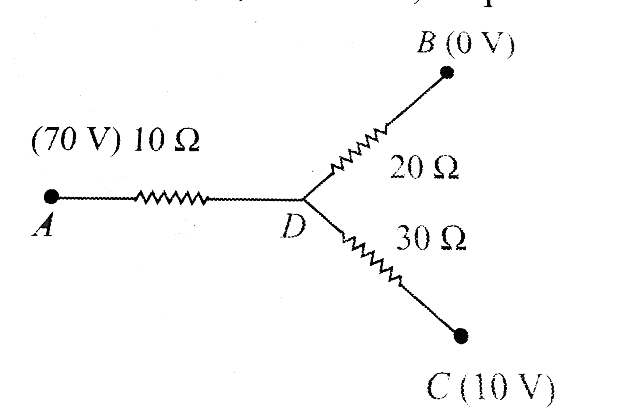 APoint D is at a potential of 40 V.BThe currents in the sections AD, DB, DC are in the ratio 3 : 2 : 1CThe currents in the section AD, DB, DC are in the ratio 1 : 2 : 3.DThe network draws a total power of 200 W.
For the network shown in figure, points A, B and C are at potentials of 70 V, zero and 10 V respectively
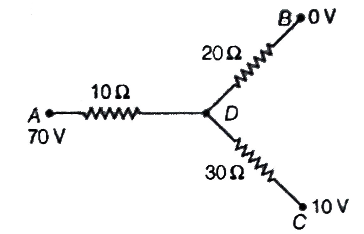 Apoint D is at a potential of 40 VBthe currents in the sections AD, DB and DC are in the ratio 4:3:2Cthe current in the sections AD, DB and DC are in the ratio 1:2:3Dthe network draws a total power of 100 W
The p.d (VB−VC between two point from C to B
Adoes not depend on the pathBdepends on the pathCdepends on test chargeDindependent of electric field
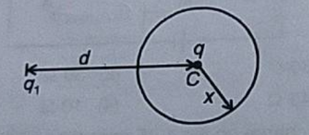
Inside a neutral hollow conducting sphere of radius X and centre C, a point charge q is placed as shown in the figure. Another point charge q1, is placed outside the sphere at distance d from centre. The net- electrostatic force on charge q placed at the centre is K=14πε0
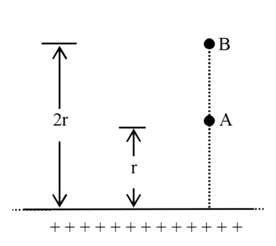
View Solution‘A point charge +Q is placed at point O as shown in the figure. Is the potential difference VA–VB positive.

View SolutionAn infinitely long line of linear charge density λ is shown in the figure. The potential difference VA−VB between the two points A and B is
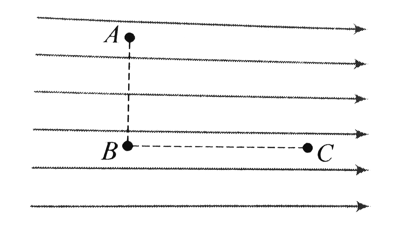
View SolutionFigure shown three points A,B and C in a region of unifrom electric field →E. The line AB is perpendicular and BC is parallel to the field lines. Then which of the following holds good. Where VA,VB and VC represenet the electric potential at points A,B and C respectively
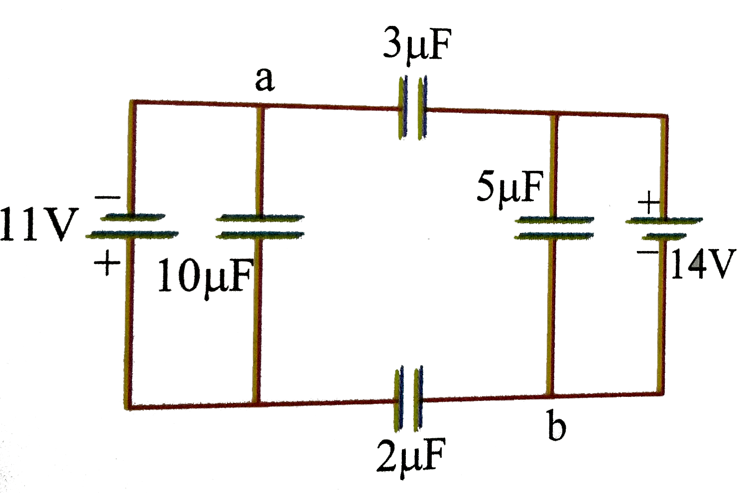
View SolutionFour capacitors and two batteries are connected as shown in the diagram. If Va and Vb denote the potentials of the points 'a' and 'b' then
 .
.
View Solution
