(a) Obtain the condition under which the current flowing in the current detecing device used in the circuit shown in figure, becomes zero.
(b) Describe briefly the device, based on the above condition. Draw a circuit diagram for this device and discuss, in brief, how it is used for finding as unknown resistance.
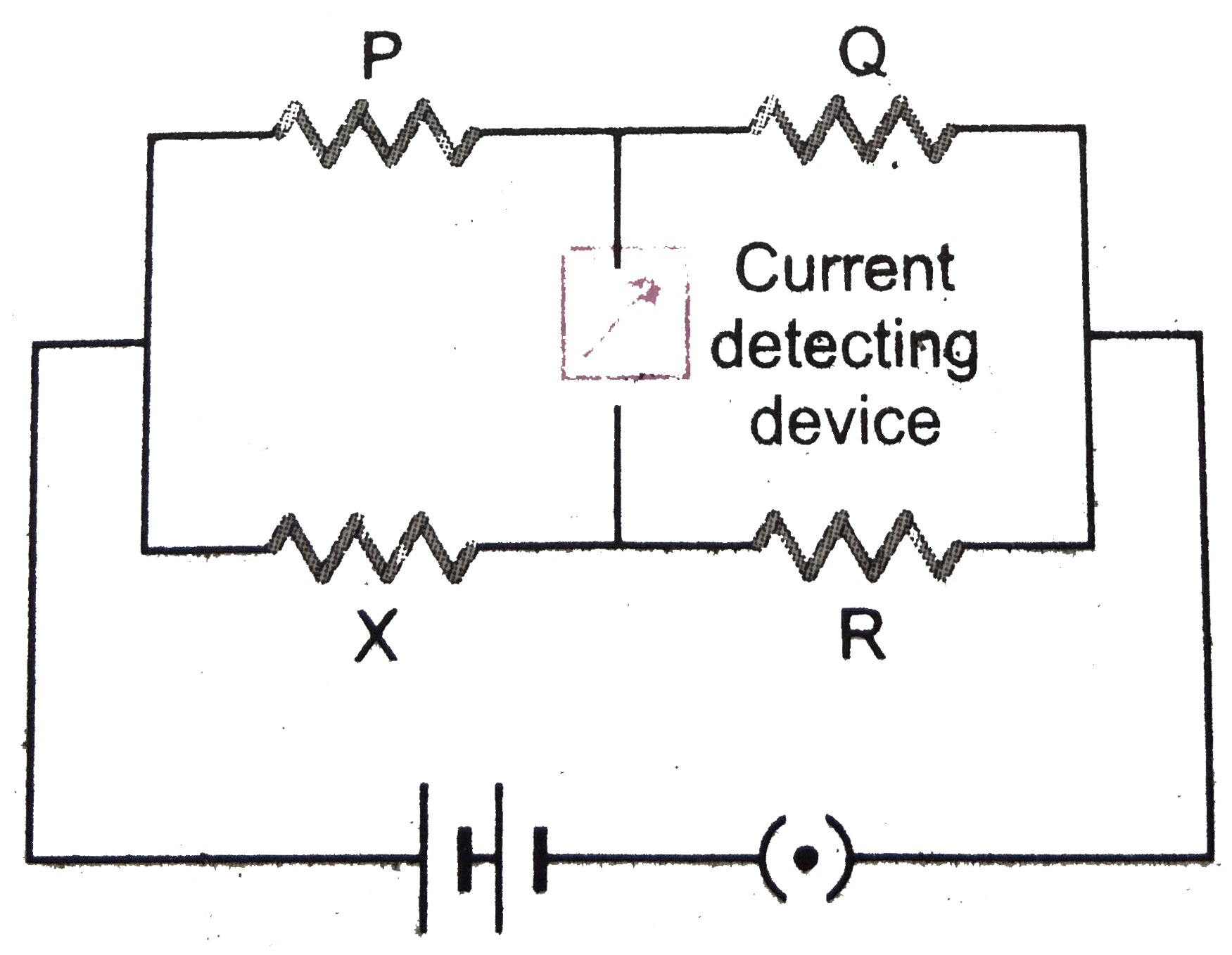
Step by step video & image solution for (a) Obtain the condition under which the current flowing in the current detecing device used in the circuit shown in figure, becomes zero. (b) Describe briefly the device, based on the above condition. Draw a circuit diagram for this device and discuss, in brief, how it is used for finding as unknown resistance. by Physics experts to help you in doubts & scoring excellent marks in Class 12 exams.
Updated on:21/07/2023Similar Questions
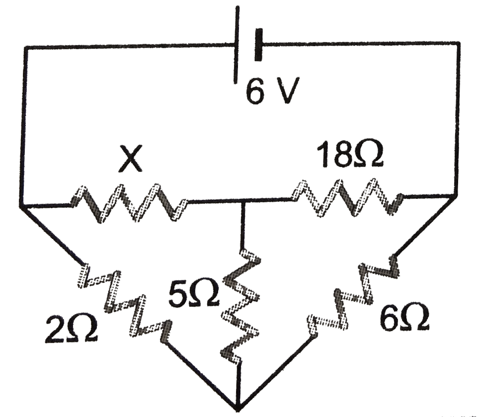
Find out the magnitude of resistance X in the circuit shown in figure, When no current flows through the 5Ω resistance
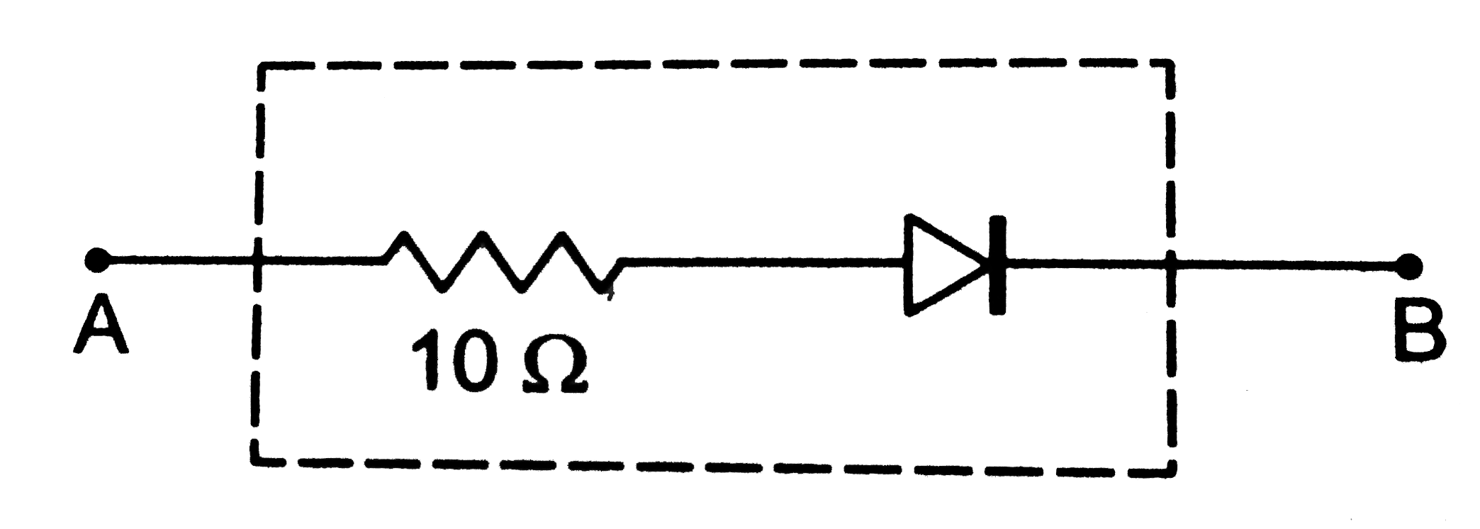
View SolutionDraw the current-voltage characteristics for the device shown in figure between the terminal A and B.

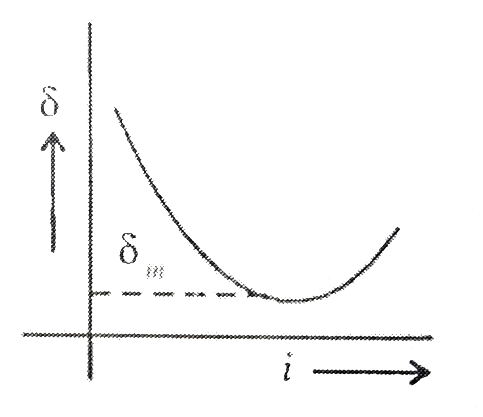
View Solution(a) The relation, between the angle of incidence :(i) and the corresponding , angle of deviation (δ) , for a certain optical decice, is represented by the graph shown in the figure. Identify this device. Draw a ray diagram for this device and use it for obtaining and expression for the refractive index of the material of this device in terms of an angle characteristic of the device and the angle, marked as δm, in the graph.
(b) Based on Huuygen's construction , draw the shape of a plane wavefront as it gets refracted on passing through a convex lens.
View SolutionWrite the principle of working of a potentiometer. Describe briefly, with the help of a circuit diagram, how a potentiometer is used to determine the internal resistance of a given cell.
View SolutionAssertion : In the circuit shown in figure, current in wire ab will become zero as soon as switch is opened.
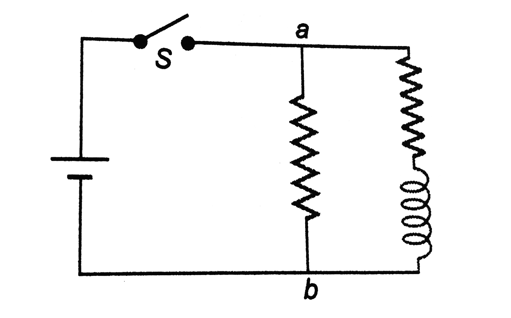
Reason : A resistance does not oppose increase or decrease of current through it.
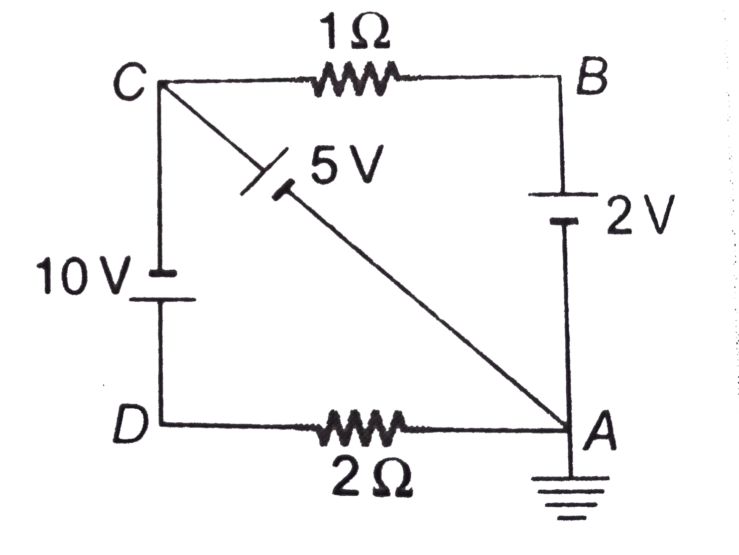
View SolutionIn the circuit shown in figure find the potentials of A,B,C and D and the current through 1Ω and 2Ω resistance.
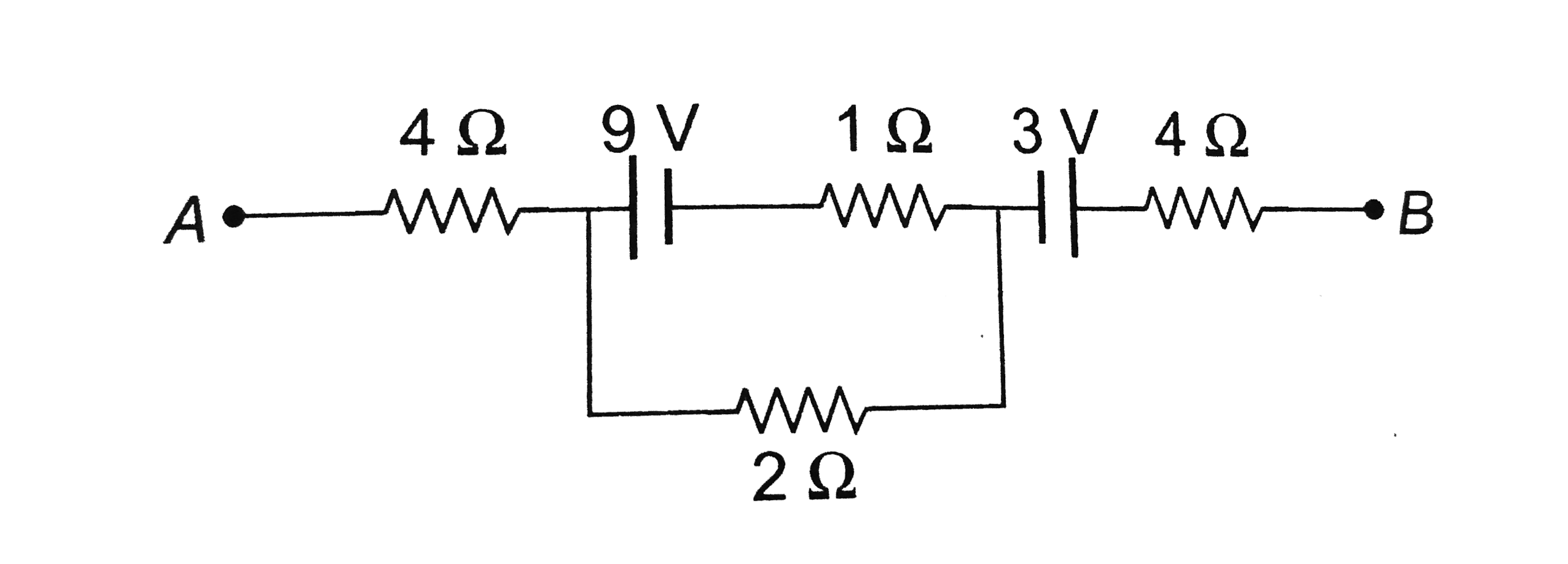
View SolutionThe potential difference between the points A and B in the circuit shown is 16 V, Which is/are the correct statement(s) out of the following?
View SolutionIn the circuit shown in figure find:
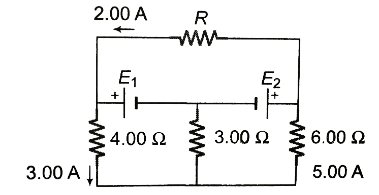
a. the current in the 3.00Ω resistor,b. the unknown emfsE1 and E2 and c the resistance R.
View SolutionDetermine the potential difference VA−VB between point A and B of the circuit shown in figure . Under what condition is it equal to zero ?
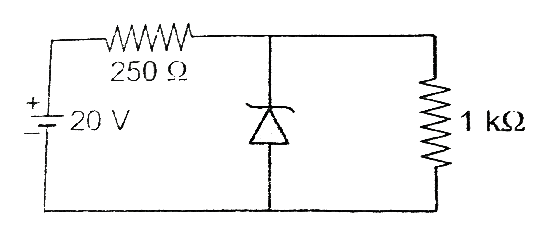
View SolutionA zener diode having breakdown voltage equal to 15V, is used in a voltage regulator circuit shown in figure. Find the current through the diode.
View Solution
