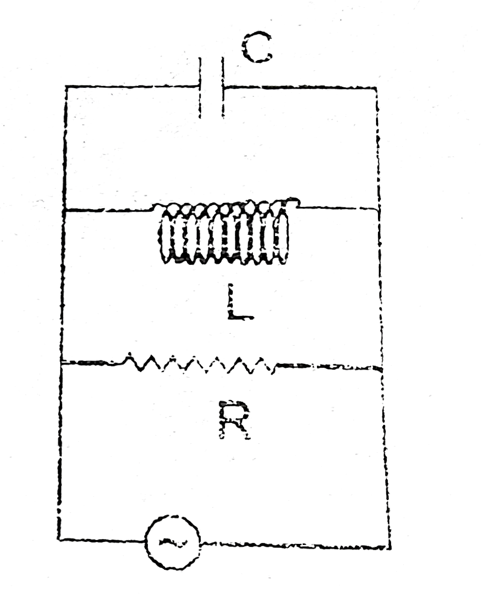
A series LR circuit is connected to an ac source of frequency ω and the inductive reactance is equal to 2R. A capacitance of capacitive reactance equal to R is added in series with L and R. The ratio of the new power factor to the old one is
√23
√25
√32
√52
The correct Answer is:D
To solve the problem step by step, we will analyze the series LR circuit and then the modified circuit with the added capacitor. We will calculate the power factors for both cases and find the ratio of the new power factor to the old one.
Step 1: Analyze the original LR circuit
In the original LR circuit:
- The inductive reactance XL is given as 2R.
- The resistance R remains the same.
The impedance Z of the LR circuit can be calculated using the formula:
Z=√R2+X2L
Substituting XL=2R:
Z=√R2+(2R)2=√R2+4R2=√5R2=R√5
Step 2: Calculate the power factor for the original LR circuit
The power factor pf is defined as:
pf=cosϕ=RZ
Substituting the values:
pfold=RR√5=1√5
Step 3: Analyze the modified circuit with added capacitor
In the modified circuit:
- The capacitive reactance XC is given as R.
- The inductive reactance XL remains 2R.
The total reactance X in the modified circuit is:
X=XL−XC=2R−R=R
Now, we can calculate the new impedance Z′:
Z′=√R2+X2=√R2+R2=√2R2=R√2
Step 4: Calculate the power factor for the modified circuit
The new power factor pf′ is:
pfnew=cosϕ′=RZ′=RR√2=1√2
Step 5: Find the ratio of the new power factor to the old power factor
Now, we need to find the ratio of the new power factor to the old power factor:
Ratio=pfnewpfold=1√21√5=√5√2=√52
Final Answer
The ratio of the new power factor to the old power factor is:
√52
In the original LR circuit:
- The inductive reactance XL is given as 2R.
- The resistance R remains the same.
Z=√R2+X2L
Substituting XL=2R:
Z=√R2+(2R)2=√R2+4R2=√5R2=R√5
The power factor pf is defined as:
pf=cosϕ=RZ
Substituting the values:
pfold=RR√5=1√5
In the modified circuit:
- The capacitive reactance XC is given as R.
- The inductive reactance XL remains 2R.
X=XL−XC=2R−R=R
Z′=√R2+X2=√R2+R2=√2R2=R√2
The new power factor pf′ is:
pfnew=cosϕ′=RZ′=RR√2=1√2
Now, we need to find the ratio of the new power factor to the old power factor:
Ratio=pfnewpfold=1√21√5=√5√2=√52
The ratio of the new power factor to the old power factor is:
√52
Topper's Solved these Questions
Similar Questions
In a seris LCR circuit, the inductive reactance (XL) is 10Ω and the capacitive reactance (XC) is 4Ω. The resistance (R) in the circuit is 6Ω. The power factor of the circuit is :
View SolutionA series RLC circuit is connected to an AC supply 220 V, 50 Hz. The value of R is 10 Ω . The value of capacitive reactance of capacitor and incuctive reactance of inductor are 15 Ω and 20Ω respectively . Calculate the value of current in the circuit.
View Solution
Knowledge Check
Statement I : In series LCR circuit , the resonance occurs at one frequency only.
Statement II : At this frequency, inductive reactance is equal to capacitative reactance.AIf both Statement- I and Statement- II are true, and Statement - II is the correct explanation of Statement– I.BIf both Statement - I and Statement - II are true but Statement - II is not the correct explanation of Statement – I.CIf Statement - I is true but Statement - II is false.DIf Statement - I is false but Statement - II is true.Series LCR circuit is connected to an AC source of angular frequency ω. Current flowing in the circuit is found to lead the voltage by π/4. Magnitude of capacitance is
A1ω2(L+R)B1ω(L+R)C1ω2L+ωRD1ωL+ω2RA series combination of R,LC is connected to an a.c source. If the resistance is 3Ω and the reactance is 4Ω, the power factor of the circuit is
A0.4B0.6C0.8D1.0
In series LR circuit, XL=3R. Now a capacitor with XC=R is added in series. The ratio of new to old power factor
View SolutionA variable capacitor is connected to an ac source. What effect does decreasing the capacitance have on the reactance and current in this circuit?
View SolutionPower dissipated in an L−C−R series circuit connected to an AC source of emf ε is
View SolutionA resistance (R) = 12 Omega, inductance (L) = 2 henry and capacitive reactance C = 5 mF are connected in series to an ac generator
View SolutionIf for above circuit the capacitive reactance is two times of inductive Reactance, and resistance R is equal to inductance Reactance then power factor of circuit is .

View Solution
