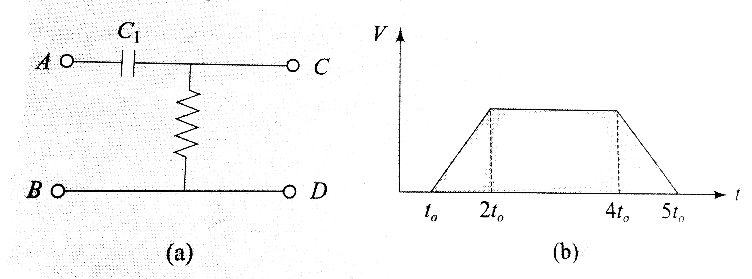
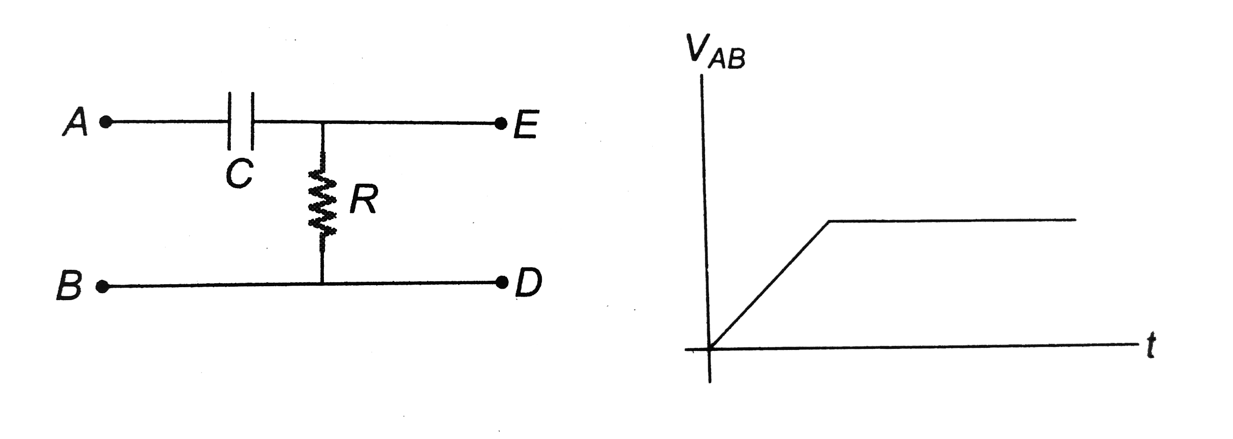
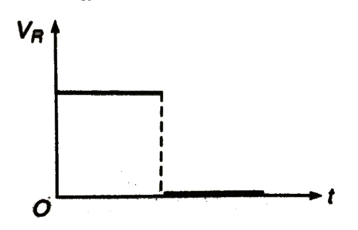
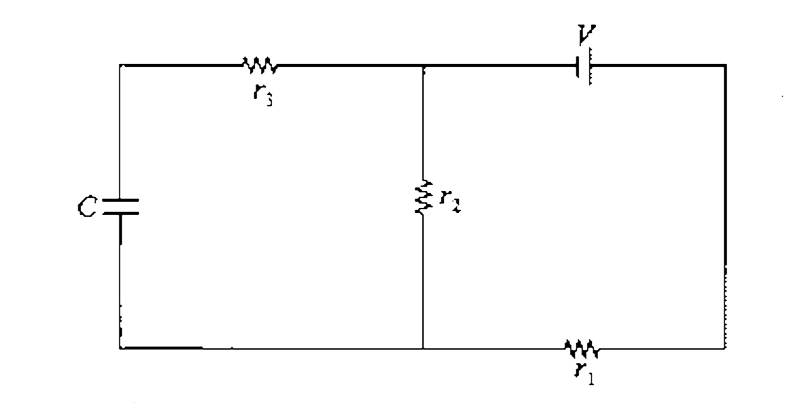
A time varying voltage is applied to the clamps and such that voltage across the capacitor plates is as shown in the figure. Plot the time dependence of voltage across the terminals of the esistance and .
Video Solution
Text Solution
The correct Answer is:A
From to
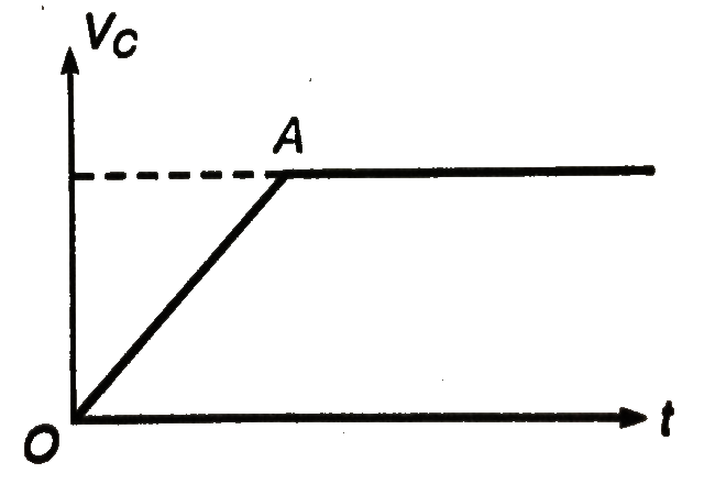
.
From A onwards
or
Therefore versus t graph is as showin in figure
|
Topper's Solved these Questions
- CAPACITORSBOOK - DC PANDEYCHAPTER - CAPACITORSEXERCISE - OBJECTIVE_TYPE
1 Videos
- CAPACITORSBOOK - DC PANDEYCHAPTER - CAPACITORSEXERCISE - OBJECTIVE_TYPE
1 Videos
- ATOMSBOOK - DC PANDEYCHAPTER - ATOMSEXERCISE - MEDICAL ENTRANCES GALLERY
42 Videos
- COMMUNICATION SYSTEMBOOK - DC PANDEYCHAPTER - COMMUNICATION SYSTEMEXERCISE - Subjective
11 Videos
Similar Questions
Knowledge Check
If A.C. voltage is applied to a pure capacitor, then votage across the capacitor ………….. .
Aleads the current by phase angle (π2) rad.Bleads the current by phase angle (π) rad.Clags behind the current by phase angle (π2)rad.Dlags behind the current by phase angle (π) rad.A time varying voltage is applied across A & B such that voltage across capacitor is given by VC=2sin2t. What is maximum potential difference across the reistance?
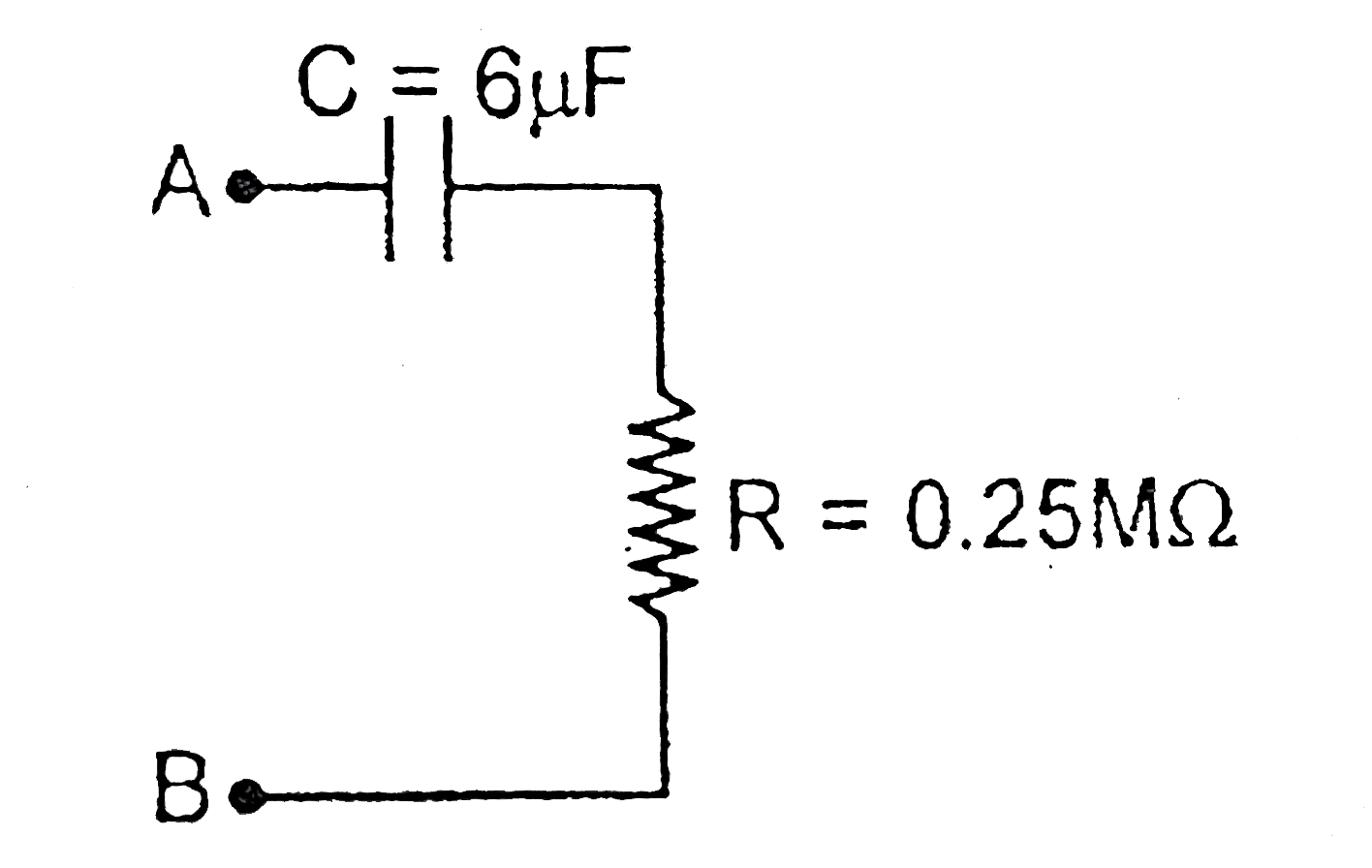 A9VB18VC3VD6V
Let q be the charge on the capacitor at any time t. The voltage V across the capacitor is
AVmsinωt=qCBVmcosωt=2VCCVmcosωt=q2CDVmsinωt=2qC
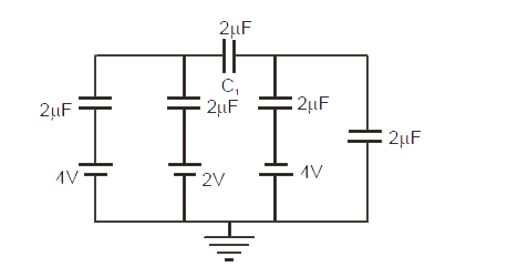 Find voltage across capacitor C1.
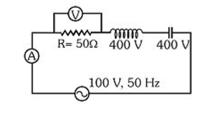
View SolutionIn given LCR circuit, the voltage across the terminals of a resistance & current will be–
View SolutionIf a voltage V is applied across the bulbs in series then
View Solution120 V AC voltage is applied to 10 ohm resistance. The peak voltage across the resistor is
View SolutionIn the circuit shown in figure, the final voltage drop across the capacitor C is :
View Solution

