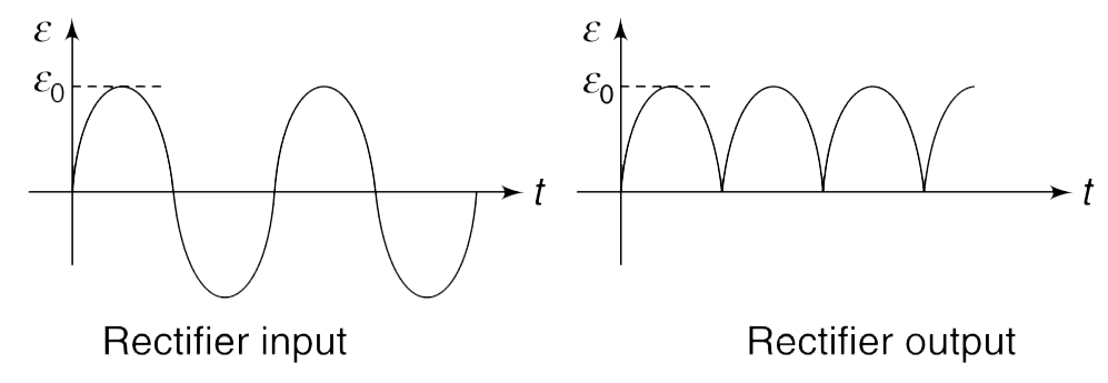
A transformer with 20 turns in its secondary coil is used to step down the input 220 V ac emf. The output of the transformer is fed to a rectifier circuit which convents the ac input into dc output. The input and output of rectifier are as shown in Figure (there is no change in peak voltage). The rectifier output has an average emf of 8.98 volt. Calculate the number of turns in the primary coil of the transformer.

The correct Answer is:440
Step by step video, text & image solution for A transformer with 20 turns in its secondary coil is used to step down the input 220 V ac emf. The output of the transformer is fed to a rectifier circuit which convents the ac input into dc output. The input and output of rectifier are as shown in Figure (there is no change in peak voltage). The rectifier output has an average emf of 8.98 volt. Calculate the number of turns in the primary coil of the transformer. by Physics experts to help you in doubts & scoring excellent marks in Class 12 exams.
Topper's Solved these Questions
Similar Questions
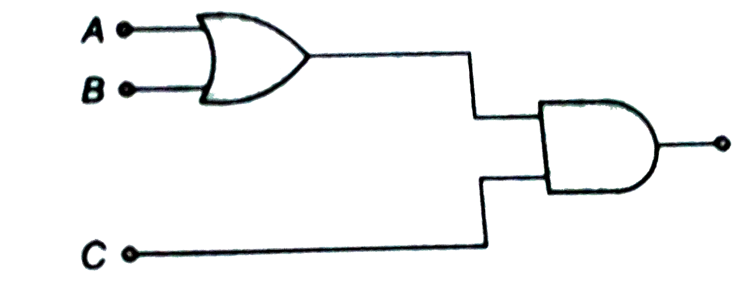
To get an output 1 from the circuit shown in figure the input must be :
 View Solution
A radio set operates at 6VDC. A transformer with 18 turns in the secondary coil is used to step down the input 220VACemf→6VACemf. This ACemf is then rectified by another circuit to give 6VDC which is fed to the radio. Find the number of turns in the primary.
View Solution
Knowledge Check
- Question 1 - Select One
To get an output of 1 form the circuit shown in figure the input must be :-
_E01_514_Q01.png) Aa=1,b=0,c=1Ba=1,b=1,c=0Ca=0,b=1,c=0Da=0,b=0,c=1
Aa=1,b=0,c=1Ba=1,b=1,c=0Ca=0,b=1,c=0Da=0,b=0,c=1 - Question 2 - Select One
In the circuit givne, A, B and C are inputs and Y is the output.

The output of Y isAhigh for all the high inputsBhigh for all the low inputsChigh when A=1,B=1,C=0Dlow for all low inputs - Question 3 - Select One
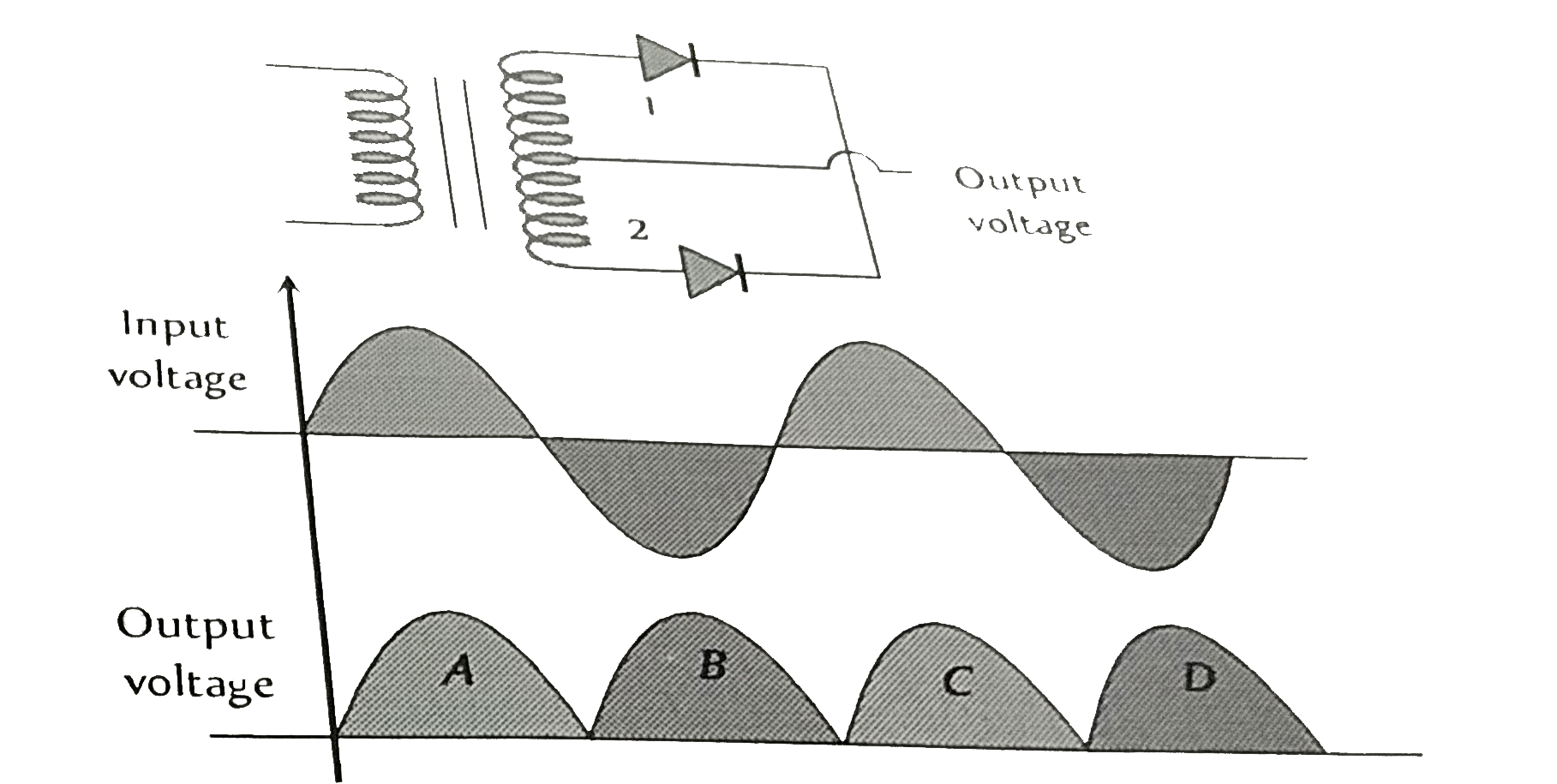
A full wave rectifier circuit along with the input and output voltages is shown in the figure

The contribution to output voltage from diode – 2 isAA,CBB,DCB,CDA,D
A rectifier is a device which is used to convert a.c. voltage input into d.c. voltage output.
View SolutionTo get an output 1 from the circuit shown in the figure, the input must be
 View Solution
To get an output 1 from the circuit shown in the figure, the input must be
 View Solution
To get an output 1 from the circuit shown in the figure, the input must be
 View Solution
In a step up transformer, the input voltage is 300 V and the output voltage is 15 KV. Then the ratio of the number of turns in the primary to that in the secondary is
View Solution

