A varying voltage is applied to the clamps AB as shown in fig. such that the voltage across the capacitor plates varies as shown in the figure. Plot the time depending on voltage across the clapes CD.
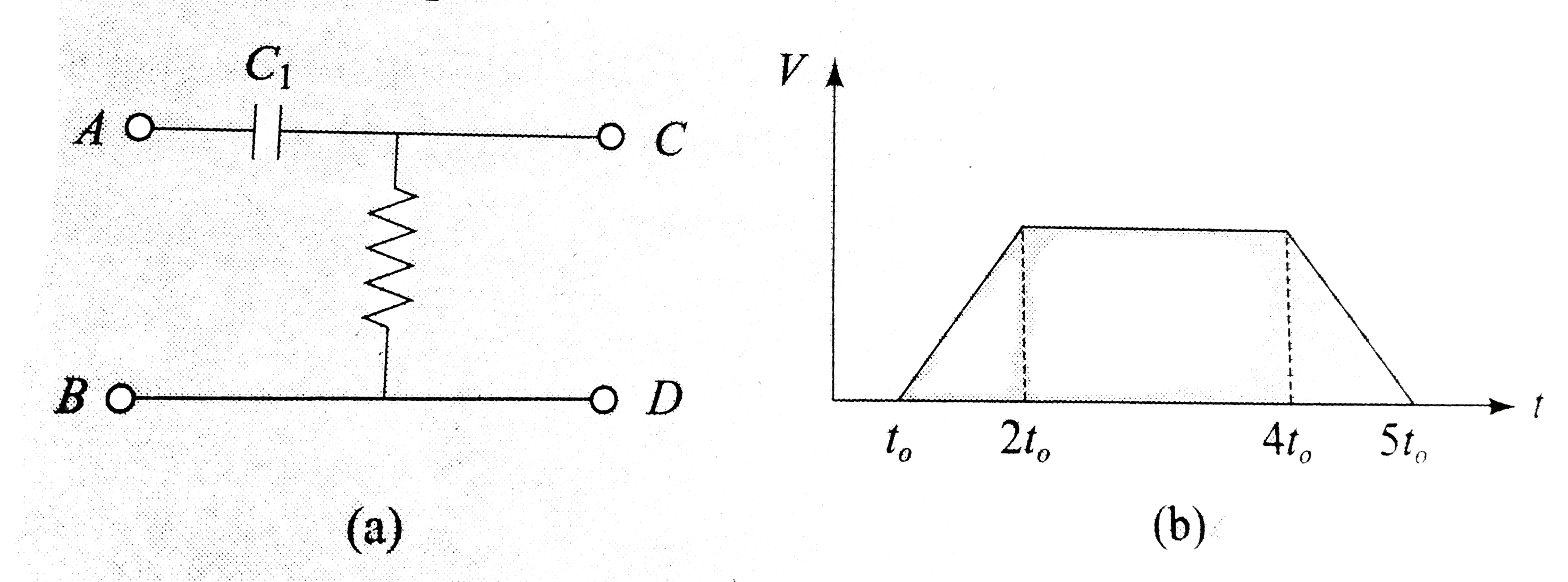

For t=t0=2t0,V=at+b
Charge on capacitor q=CV=C[at+b]
Current I=dqdtCa→constant

Potential across CD=IR=CaR→constant
Topper's Solved these Questions
- BOOK - CENGAGE PHYSICS ENGLISHCHAPTER - ELECTRIC CURRENT AND CIRCUITEXERCISE - Subjective29videos
ELECTRIC CURRENT AND CIRCUIT
- BOOK - CENGAGE PHYSICS ENGLISHCHAPTER - ELECTRIC CURRENT AND CIRCUITEXERCISE - Single Correct72videos
ELECTRIC CURRENT AND CIRCUIT
- BOOK - CENGAGE PHYSICS ENGLISHCHAPTER - ELECTRIC CURRENT AND CIRCUITEXERCISE - Exercise 5.128videos
ELECTRIC CURRENT AND CIRCUIT
- BOOK - CENGAGE PHYSICS ENGLISHCHAPTER - ELECTRIC CURRENT & CIRCUITSEXERCISE - Kirchhoff s law and simple circuits15videos
ELECTRIC CURRENT & CIRCUITS
- BOOK - CENGAGE PHYSICS ENGLISHCHAPTER - ELECTRIC FLUX AND GAUSS LAWEXERCISE - MCQ s38videos
ELECTRIC FLUX AND GAUSS LAW
Similar Questions
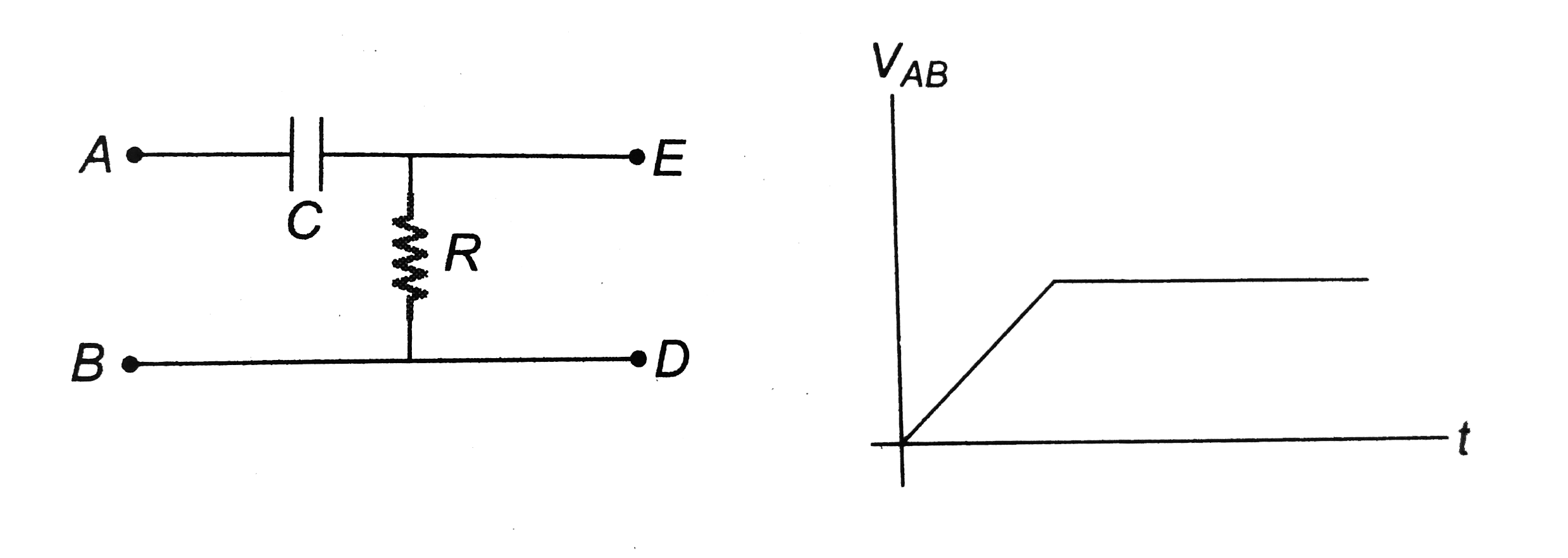
A time varying voltage is applied to the clamps A and B such that voltage across the capacitor plates is as shown in the figure. Plot the time dependence of voltage across the terminals of the esistance E and D.
 View Solution
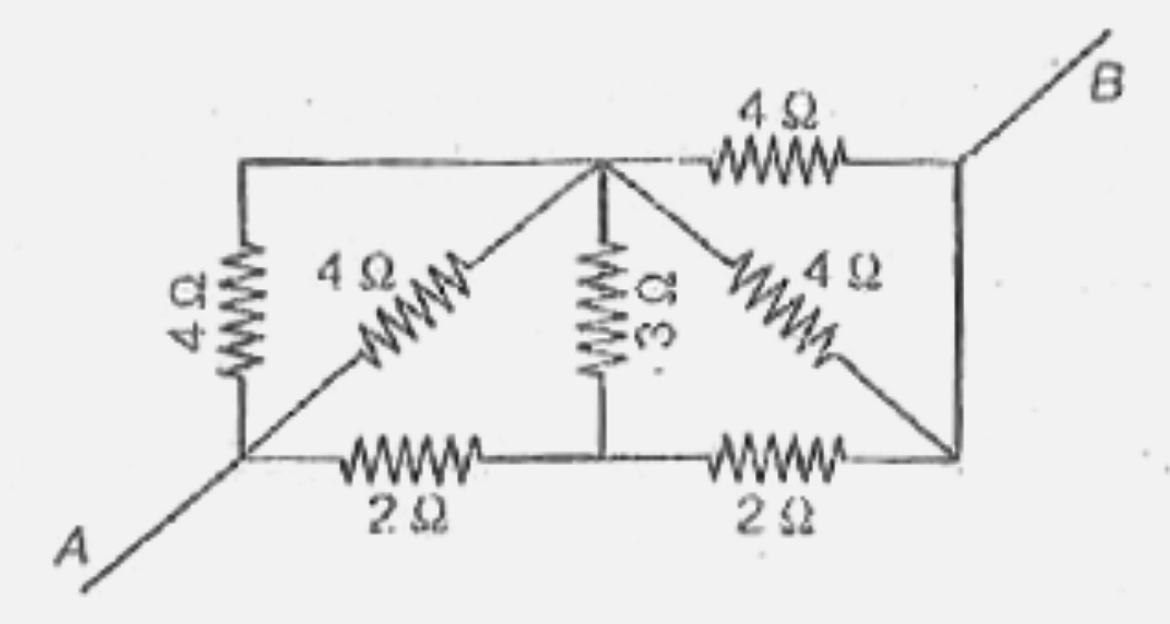
Resistance across AB as shown in figure is
 View Solution
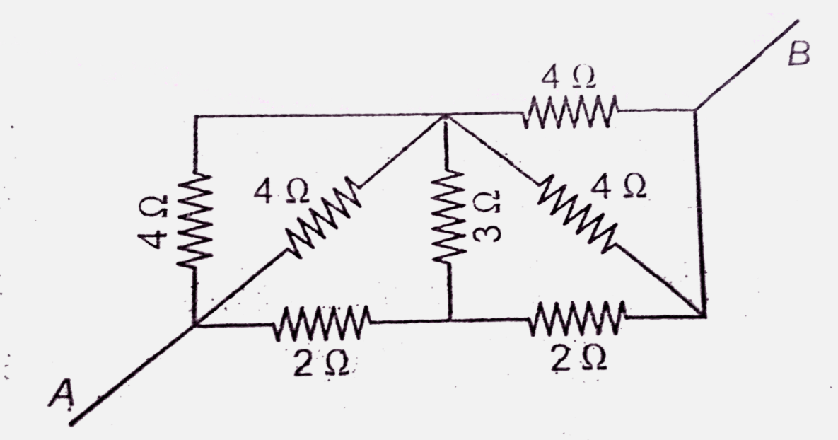
Resistance across AB as shown in figure is
 View Solution
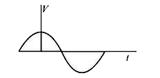
Voltage across a capacitor varies as shown in the diagram. Which diagram correctly represents the current time curve?
 View Solution
Potential difference across AB in the circuit as shown in figure.
 View Solution
For the circuit shown in figure, determine the voltage across 4Ω resistors in volt ?
 View Solution
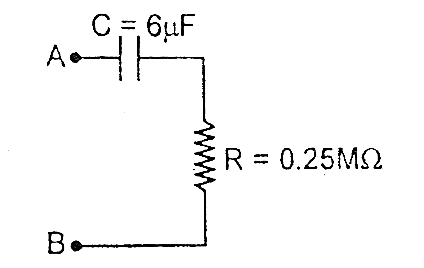
A time varying voltage is applied across A & B such that voltage across capacitor is given by VC=2sin2t. What is maximum potential difference across the reistance?
 View Solution
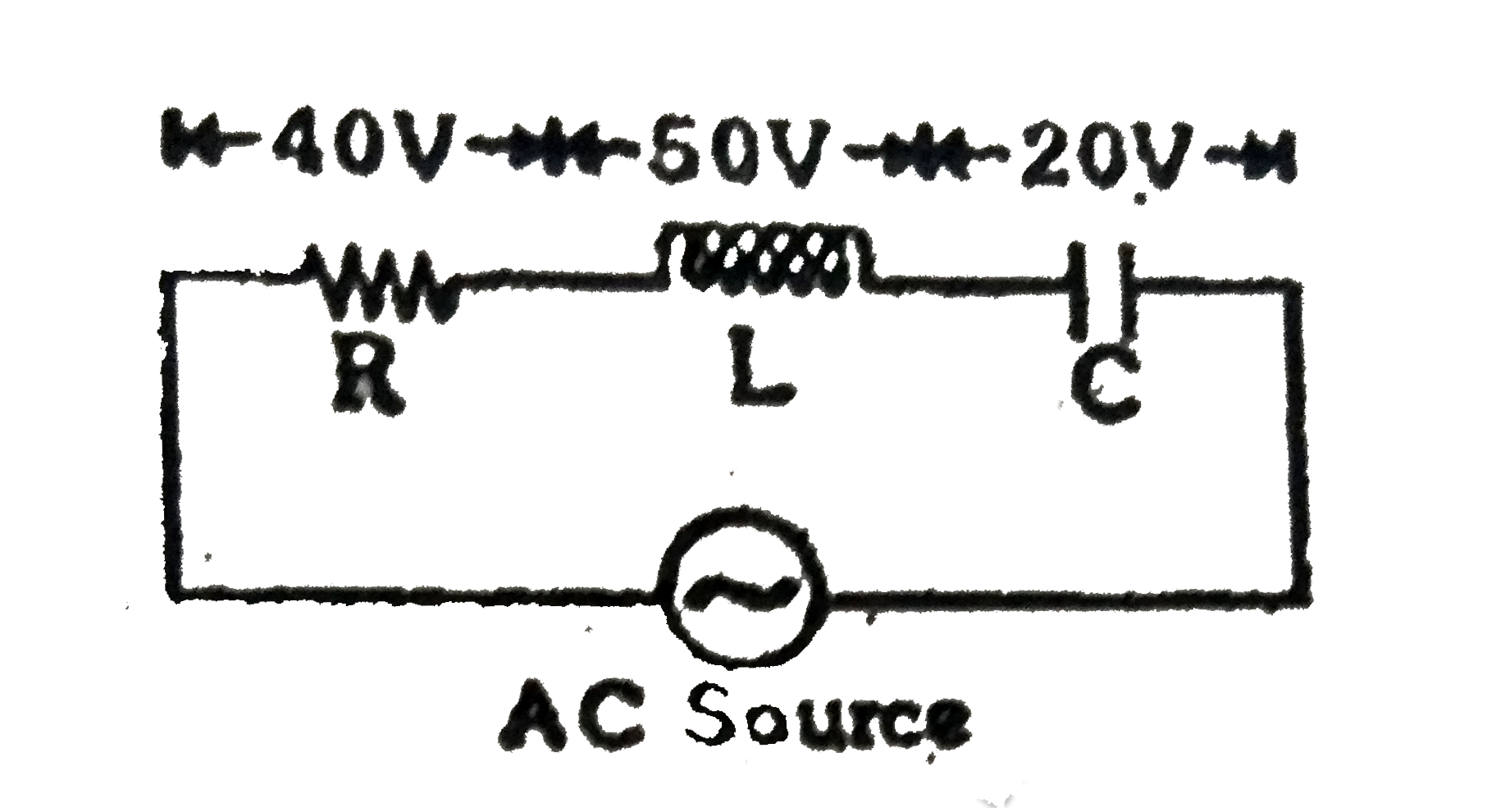
In series LCR circuit, the voltages across R, L and C are shown in the figure. The voltage of applied source
 View Solution
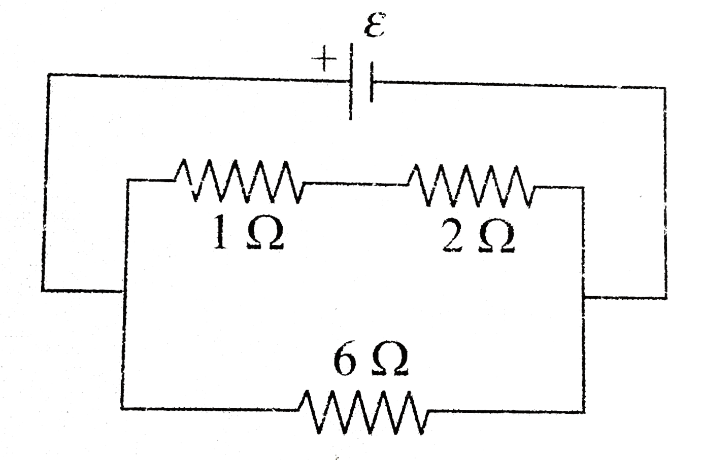
In the circuit shown in fig the voltage across the 2 Ω resistor is 12V. What is the emf of the battery and the current thorugh the 6 Ω resistor?
 View Solution
An AC voltage is applied acrss a series combination of L and R. If the voltage drop across the resistor and inductor are 20V and 15V respectiely, then applied peak voltage is
View Solution

