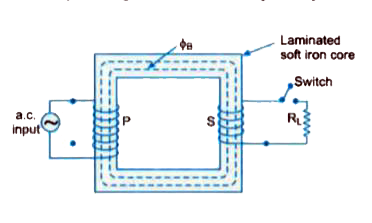
(a) With the help of a labelled digram, explain the working of a step-up transformer. Give reason to explain the following,
(i) The core of the transformer is laminated.
(ii) Thick copper wire is used in windings.
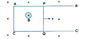
(b) A conducting rod PQ of length 20 cmn and resistance 0.1Ω rests on two smooth parallel rails of negligible resistance AA' and CC'. It can slide on the rails and the arrangement is positioned between the poles of a permanent magnet producing uniform magnetic field B=0.4T. The rails, the rod and the magnetic field are in three mutually perpendicular directions as shown in the figure. If the ends A and C of the rails are short circuited, find the
(i) external force required to move the rod with uniform velocity v= 10 cm/s, and
(ii) power required to do so. 
(a) A step up transformer is shown here. It consists of two coils of enamelled copper wire wound on a laminated soft iron core. Number of turns in secondary coil is greater than that in primary coil
When an alternating emf/voltage source is applied across the P coil, the input current and, hence, magnetic flux through P coil soft iron core keeps on changing with time. The changing magnetic flux gets linked up with S coil through the iron core, which in turn produces induced voltage across the secondary coil. It coupling of two coils is good then all flux lines across P coil link up with Scoil too. If at any time, the flux linked per unit tum of primary be ϕB then
Total magnetic flux of P coil, ϕP=NP,ϕE [where NP= Total number of turns in P coil) and instantaneous value of induced emf in P coil, εp=−dϕPdt=−NPdϕBdt
If total number of turns in S coil be NS then magnetic flux of S coil ϕs=Ns.ϕB
and instantaneous value of induced emf in S coil, εs=dϕsdt=−NsdϕBdt
For an ideal transformer |εp|= input voltage Vpandεs=Vs = output voltage obtained across secondary coil. Then,
|εs||εp|=VsVp=NsNp
Again for an ideal transformer input power output power
∴Vp.Ip=Vs.Is
⇒VsVp=IpIs=NsNp=k (the transformer ratio)
Since Ns>Np in a step up transformer, Vs>Vp) i.e, transformer ratio k has a value greater than unity.
(i) The core of the transformer is laminated one so as to minimise setting up of eddy currents in it.
(ii) Thick copper wire is used in windings of coils so that resistance of the coils is small and least possible electrical energy is dissipated as heat due to Joule.s heating.
(b) Her length of rod l=20cm =0.2m, resistance R=0.1Ω, magnetic field B=0.4T and uniform
velocity or rod v=10cms−1=0.1ms−1
(i) Induced current I=BlvR and hence force required to move the rod
F=BIl=B2l2vR=(0.4)2×(0.2)2x(0.1)0.1=6.4×10⁻⁴n
(ii) Power required P=Fv=(6.4×10−4)×0.1=6.4×10⁻⁵W

Similar Questions
Explain the reason why laminated cores are used in transformers.
View SolutionExplain with the help of a labelled diagram the working of a transformer.
View SolutionWhat is the principle of transformer?
(b) Explain how laminating the core of a transformer helps to reduce eddy current loss.
(c ) Why the primary and secondary coils of a transformer and preferably wound on same core?
View SolutionA transformer core is laminated to reduce
View SolutionExplain the working principal of a step - up transformer.
View SolutionA conducting rod PQ of length 20 cm and resistance 0.1 Omega rests on two smooth parallel rqails of negligible resistance AA' and CC'. It can slide on the rails and the arrangement is positioned betwaeen the poles of a permanent magnet producing unifrom magnetic field B=0.4 T. The rails, the rod and the magneitc field are in the three mutually perpendicular directions as shown in the figure. if hte ends A and C of the rails are short cicuited, find the External force required to move the rod with uniform velocity v=10cm/s.
View SolutionA conducting rod PQ of length 20 cm and resistance 0.1 Omega rests on two smooth parallel rqails of negligible resistance AA' and CC'. It can slide on the rails and the arrangement is positioned betwaeen the poles of a permanent magnet producing unifrom magnetic field B=0.4 T. The rails, the rod and the magneitc field are in the three mutually perpendicular directions as shown in the figure. if hte ends A and C of the rails are short cicuited, find the Power required to move the rod with velocity v= 10 cm/s
View SolutionCan we a transformer be used to step up or step down a D.C. voltage? Explain.
View Solution
