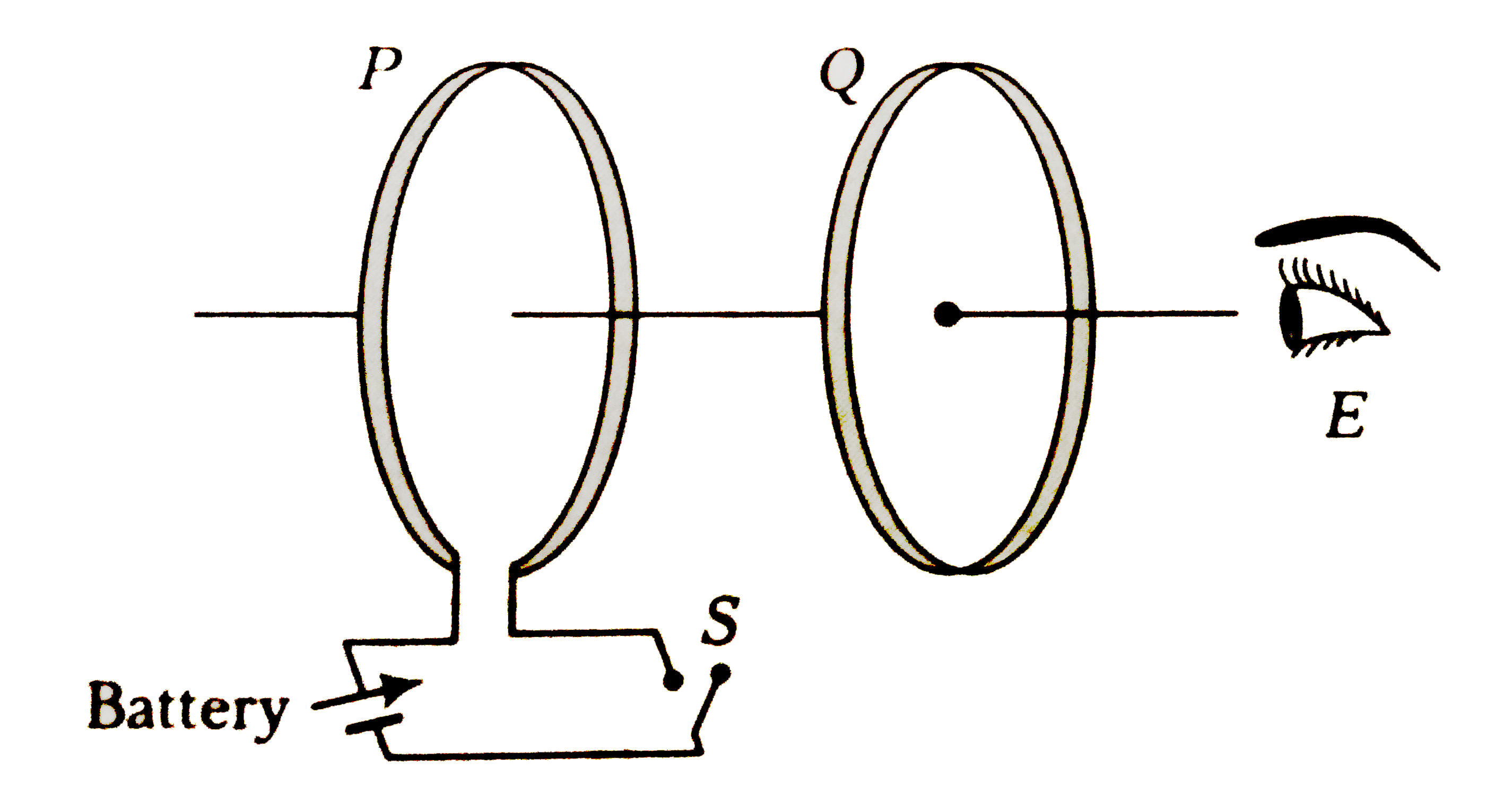
As shown in the figure, P and Q are two coaxial conducting loops separated by some distance. When the switch S is closed, a clockwise current IP flows in P (as seen by E) and an induced current IQ1 flows in Q. The switch remains closed for a long time. When S is opened, a current IQ2 flows in Q. then the direction IQ1andIQ2 (as seen by E) are
 .
.
respectively clockwise and anticlockwise
both clockwise
both anticlockwise
respectively anticlockwise and clockwise
The correct Answer is:D
When the switch S is closed, a clockwise current flows in P and as per Lenz's law, the induced current (IQ1) produced in Q will flow in the anticlockwise direction. When S is opened, the current IQ2 in Q2 will be in the clockwise direction. Thus it will be anticlockwise and clockwise respectively.
Topper's Solved these Questions
- ELECTROMAGNETIC INDUCTION AND ALTERNATING CURRENTS BOOK - MARVEL PUBLICATIONCHAPTER - ELECTROMAGNETIC INDUCTION AND ALTERNATING CURRENTS EXERCISE - TEST YOUR GRASP - 16
30 Videos
- ELASTICITYBOOK - MARVEL PUBLICATIONCHAPTER - ELASTICITYEXERCISE - Test Your Grasp - 5
15 Videos
- ELECTRONS AND PHOTONS BOOK - MARVEL PUBLICATIONCHAPTER - ELECTRONS AND PHOTONS EXERCISE - TEST YOUR GRASP - 17
15 Videos
Similar Questions
As shown in the figure, P and Q are two coaxial conducting loops separated by some distance. When the switch S is closed, a clockwise current IP (as seen by E) and an induced current IQ1 flows in Q. The switch remains closed for a long time. when S is opened, a current IQ2 flows in Q. Then the direction IQ1andIQ2 (as seen by E) are
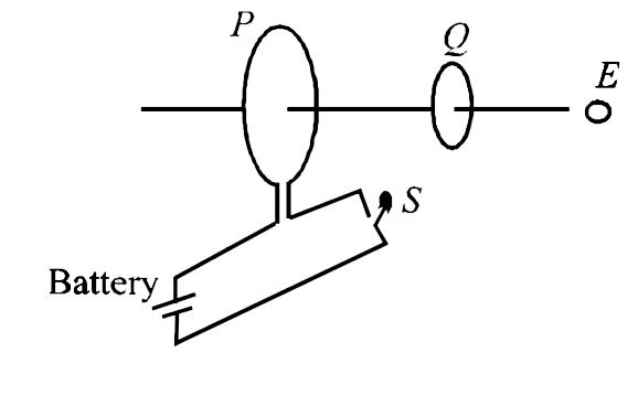
View SolutionAs shown in figure, P and Q are two co-axial conducting loops separated by some distance. When the switch S is closed, a clockwise current IP flows in P (as seen by E) and an induced current IQ1 flows in Q. The switch remains closed for a long time. When S is opened, a current IQ2 flows in Q.
Then, the directions of IQ1 and IQ2 (as seen by E) are
View Solution
Knowledge Check
As shown in the figure, P and Q are two coaxial conducting loops separated by some distance. When the switch S is closed, a clockwise current IP (as seen by E) and an induced current IQ1 flows in Q. The switch remains closed for a long time. when S is opened, a current IQ2 flows in Q. Then the direction IQ1andIQ2 (as seen by E) are
 Arespectively clockwise and anti-clockwiseBboth clockwiseCboth anti-clockwiseDrespectively anti-clockwise and clockwise
If the switch is closed then current will flow.
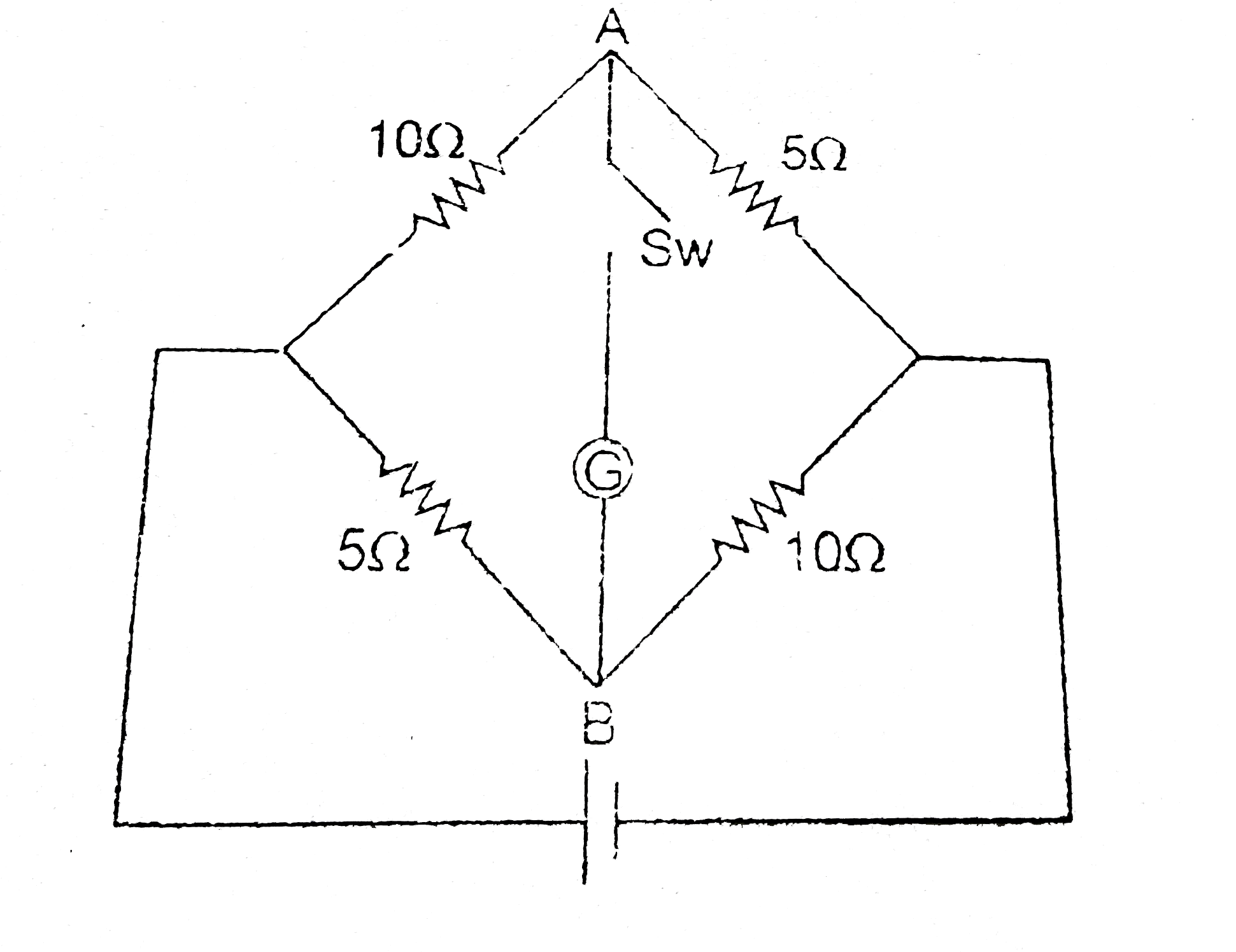 Afrom A to BBfrom B to AC0Dcannot say unless resistance of galvanometer is given
In fig. A2.27, the charge that flows from P to Q when the switch S is closed is
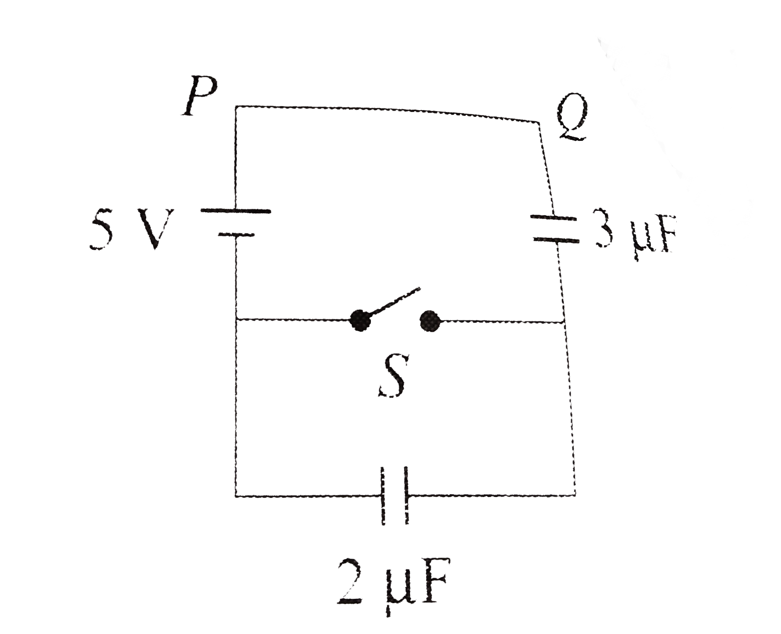 A3μCB6μCC9μCD15μC
If the switch is closed then current will flow.

View SolutionIn fig. A2.27, the charge that flows from P to Q when the switch S is closed is

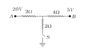
View SolutionThe potential at points A and B are maintained at 20 V and 5 V as shown. When the switch S is closed, the current that flows through it is __________ A.
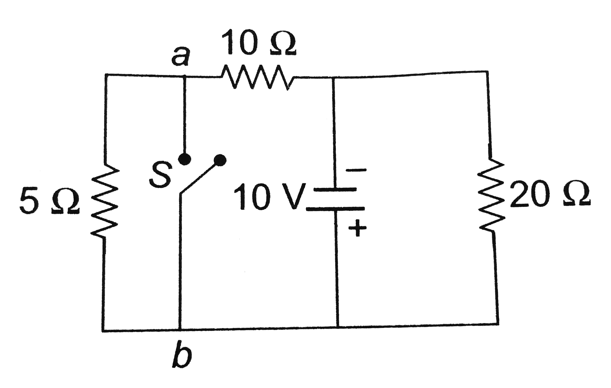
View SolutionIn the circuit shown below, the current that flows from a to b when switch S is closed is
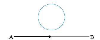
View SolutionThe current flows from A to B as shown in the figure The direction of the induced current in the loop is :
View Solution
