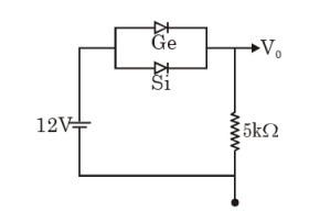
Calculate the value of output voltage V0 (in V) if the Si diode and Ge diode conduct at 0.7V and 0.3V respectively. Fig.
The correct Answer is:11.7
(i) As germanium diode conducts at lower voltage (0.3V) than silicon diode which conduct at 0.7 V, so the current will prefer to pass through germanium diode. Then
output voltage, V0=12−0.3=11.7V
and current, I=V0R=11.75×103=2.34×10⁻³A=2.34mA
(ii) When germanium diode is reverse biased, it will offer very large resistance to the current flowing through it. Now the current will flow through the silicon diode. Then
output voltage, V0=12−0.7=11.3V
and current, I=V0R=11.35×103=2.26×10⁻³A
=2.26mA
Topper's Solved these Questions
- ELECTRONIC DEVICESBOOK - PRADEEPCHAPTER - ELECTRONIC DEVICESEXERCISE - SAMPLE PROBLEM
2 Videos
- ELECTRONIC DEVICESBOOK - PRADEEPCHAPTER - ELECTRONIC DEVICESEXERCISE - CONCEPTUAL PROBLEMS
1 Videos
- ELECTROMAGNETIC WAVESBOOK - PRADEEPCHAPTER - ELECTROMAGNETIC WAVESEXERCISE - II Focus multiple choice question
5 Videos
- ELECTROSTATICSBOOK - PRADEEPCHAPTER - ELECTROSTATICSEXERCISE - ASSERTION-REASON TYPE QUESTIONS
2 Videos
Similar Questions
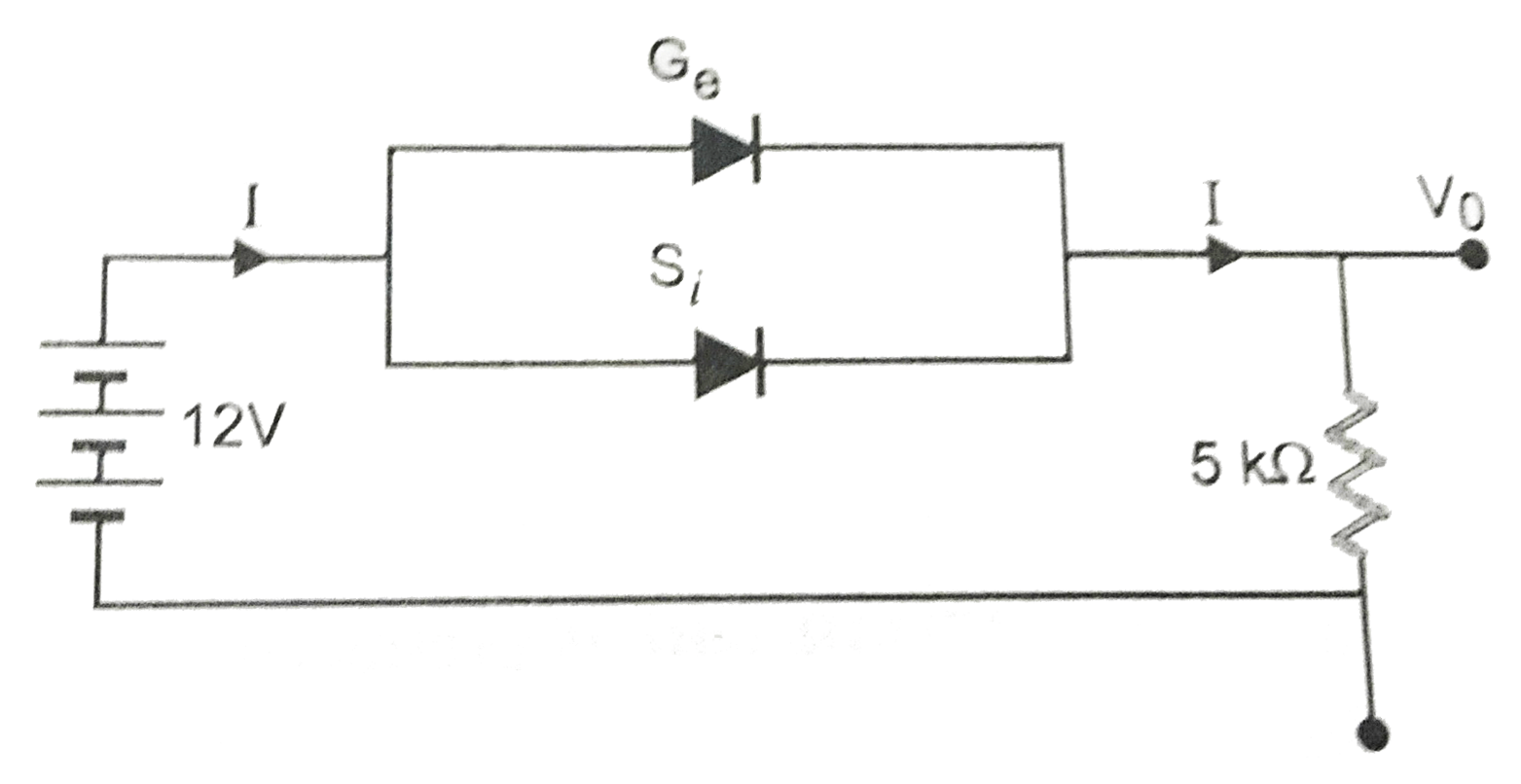
Calculate the value of output voltageV0 and I if the Si diode and the Ge diode conduct at 0.7 V and 0.3V respectively, in the circuit given in Fig. If now Ge diode connections are reversed, what will be the new values of V0 and I.
View SolutionCalculate the value of output voltage V0 (in V) if the Si diode and Ge diode conduct at 0.7V and 0.3V respectively. Fig.

View Solution
Knowledge Check
In the circuit shown in figure, the silicon and germanium diodes start conducting at 0.7 V and 0.3 V respectively. What are the values of V0 and I?
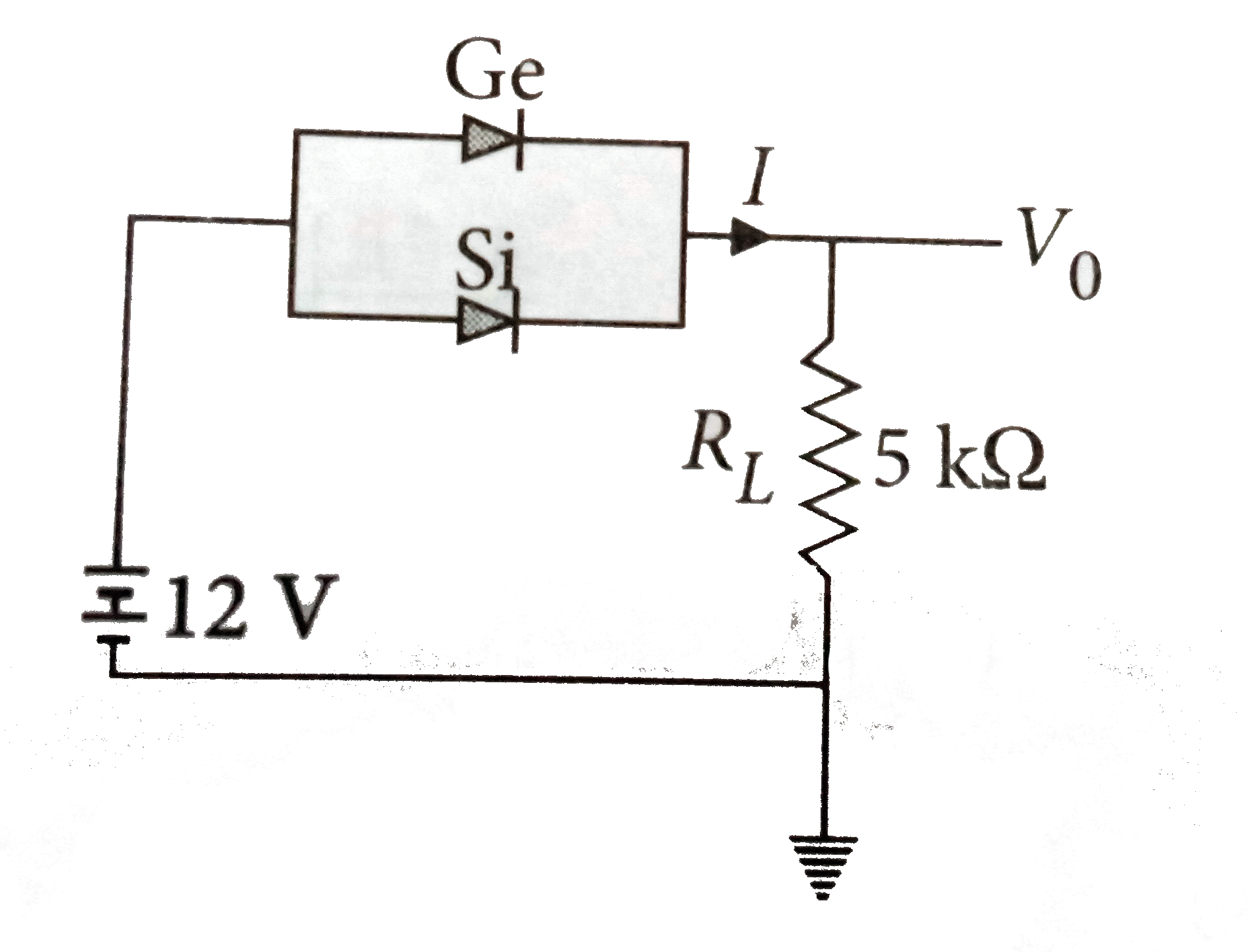 A12 V, 2.4 mAB11.7 V, 2.34 mAC11.3 V, 2.26 mAD11 V, 2.2 mA
In the circuit shown in figure the maximum output voltage V0 is
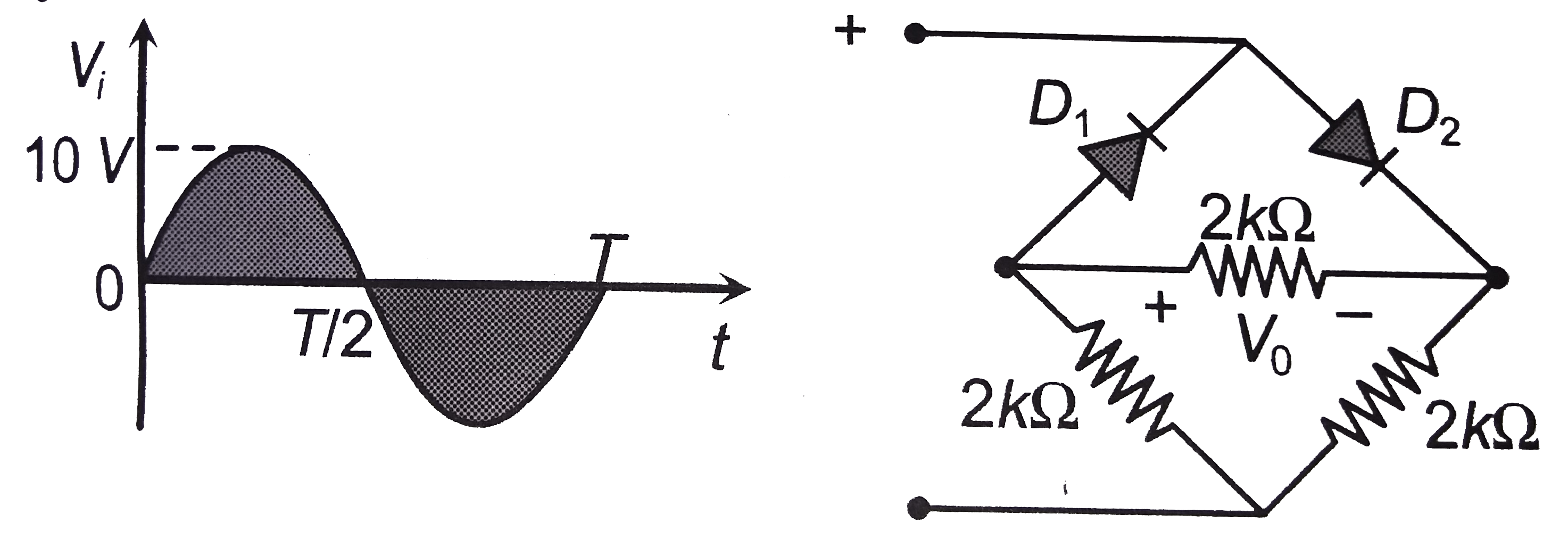 A0VB5VC10VD5√2V
Calculate the value of output voltageV0 and I if the Si diode and the Ge diode conduct at 0.7 V and 0.3V respectively, in the circuit given in Fig. If now Ge diode connections are reversed, what will be the new values of V0 and I.

View SolutionWhat is the value of output voltage V0 in the circuit shown in the figure ?
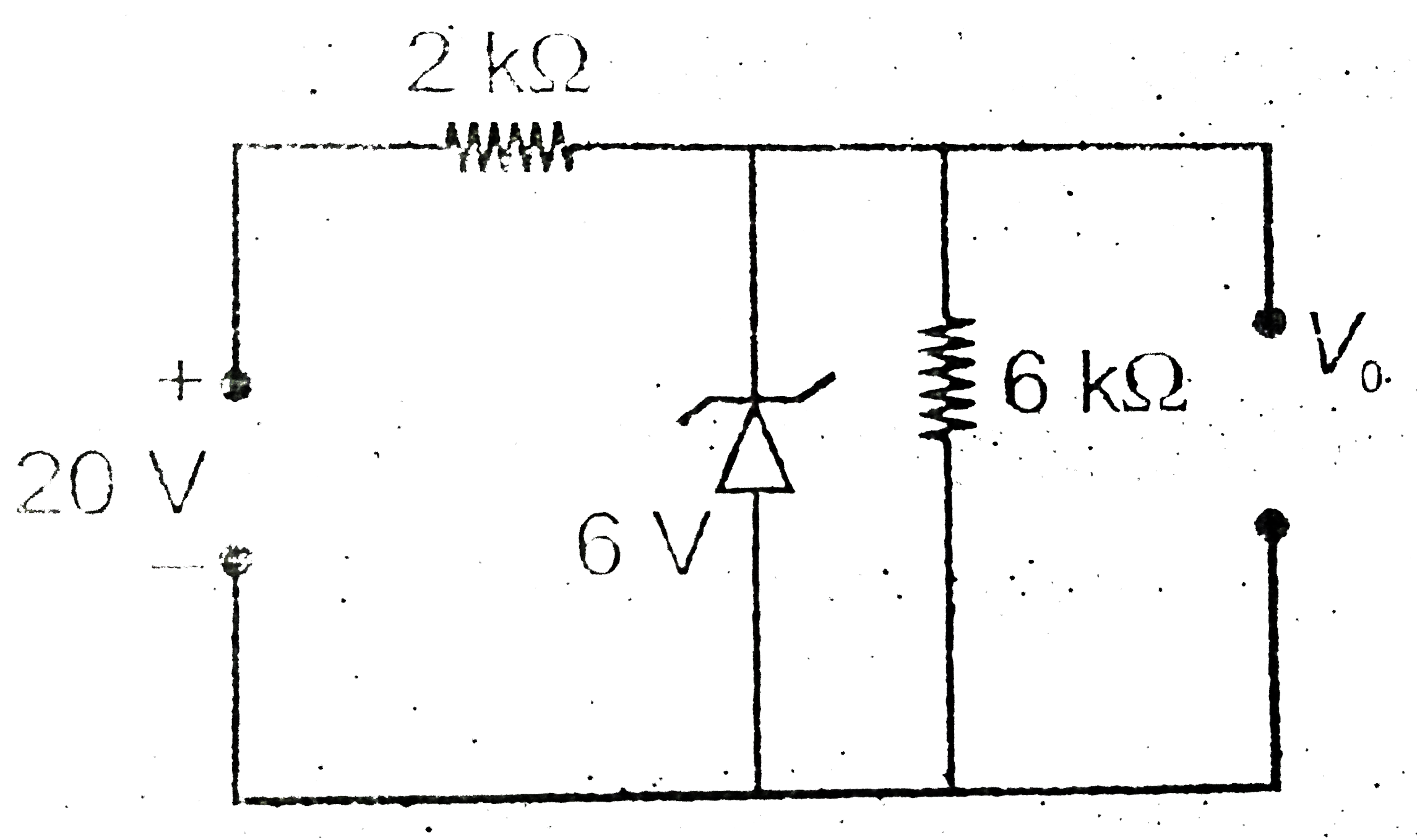
View SolutionWhat is the value of output voltage V0 in the circuit shown in the figure ?
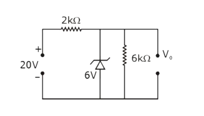
View SolutionWhat is the value of knee voltage in
(a) Ge junction diode.
(b) Si junction diode.
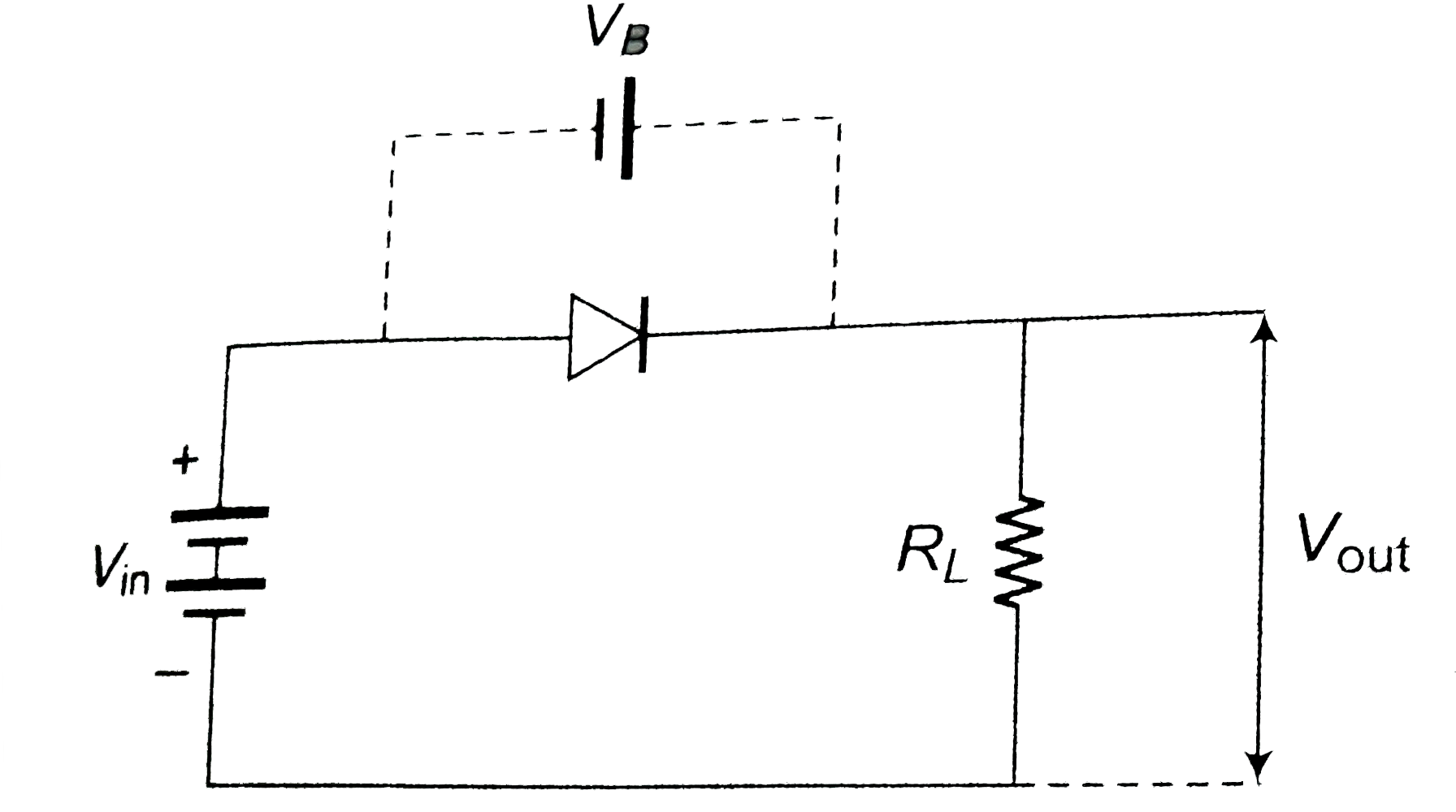
View SolutionA silicon diode is connected to a load resistance RL as shown in the figure. If V∈=15V and RL=10kΩ
(a) If barrier voltage, VB=0.7V then calculate
(i) output voltage across RL
(ii) current in diode and ltbRgt (iii) forward resistance.
(b) If diode is assumed ideal, then what will be
(i) output voltage and
(ii) output current in diode?
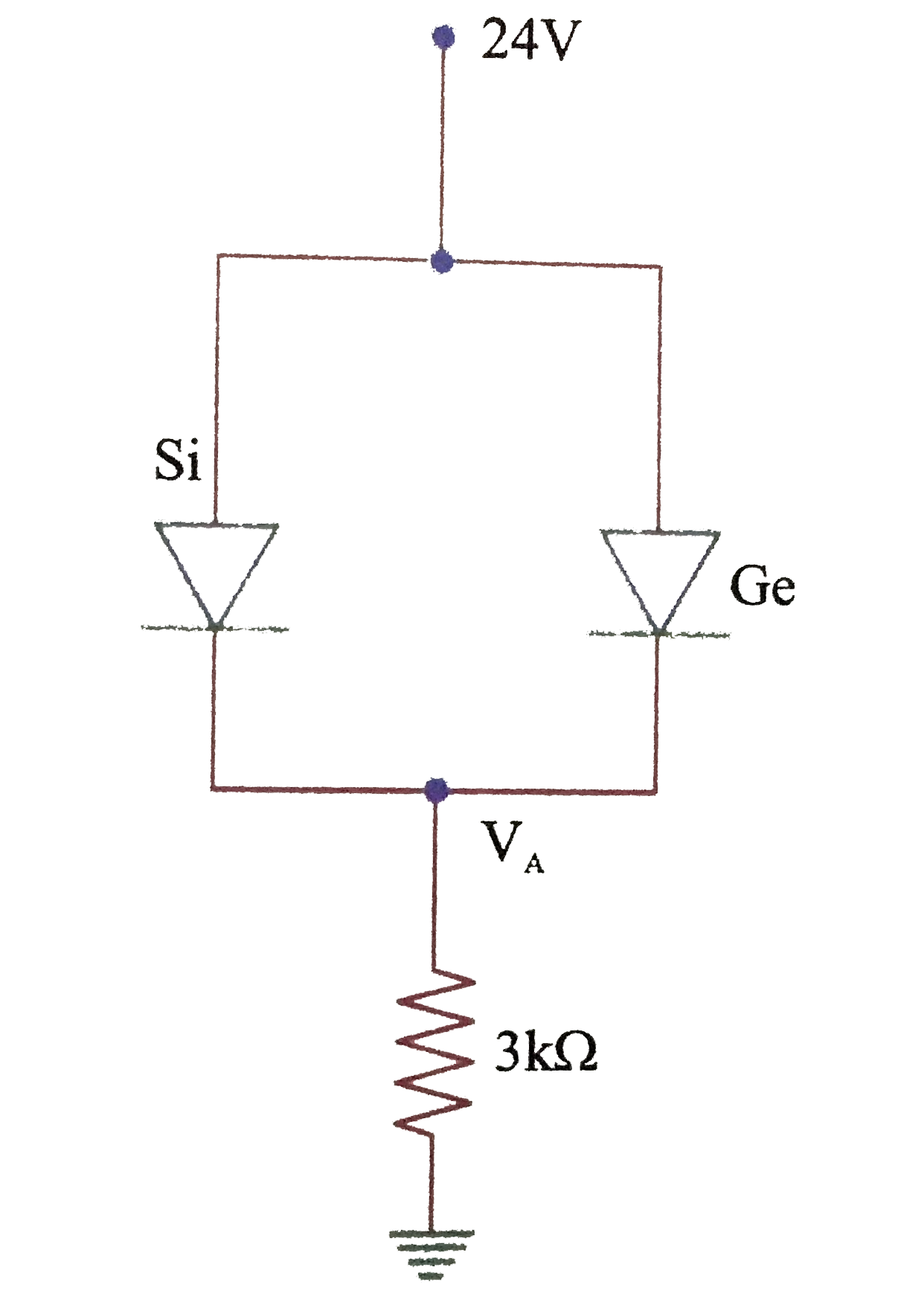
View SolutionFind the voltage VA in the curcuit shown in figure. The potential barrier for Ge is 0.3V and for Si is 0.7V
 .
.
View Solution
