Draw a circuit diagram for a bulb connected to a cell with a switch. Mark arrows in the diagram to indicate the direction of flow of current.
To draw a circuit diagram for a bulb connected to a cell with a switch and to indicate the direction of current flow, follow these steps:
1. Draw the Cell:
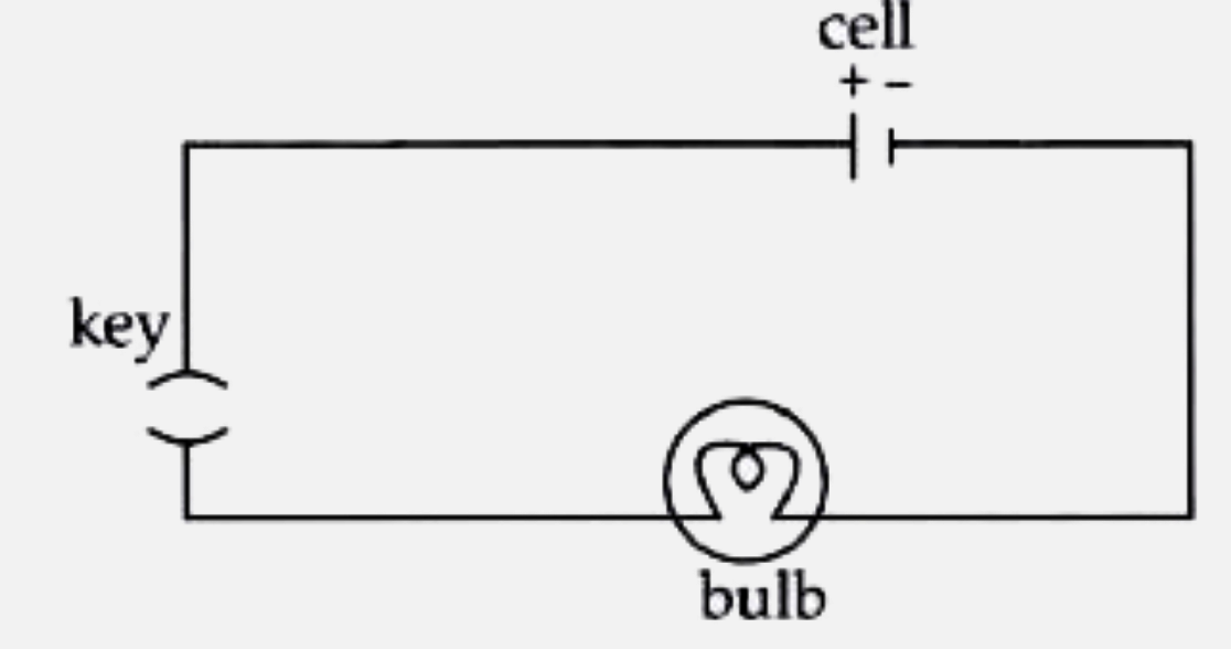
- Start by drawing the symbol for a cell. The cell is represented by two parallel lines, where one line is longer (positive terminal) and the other is shorter (negative terminal).
- Label the longer line as the positive terminal (+) and the shorter line as the negative terminal (-).
2. Draw the Bulb:
- Next, draw the symbol for a bulb. The bulb is represented by a circle with a small line at the bottom.
- Place the bulb in the circuit diagram, ensuring it is connected to the cell.
3. Draw the Switch:
- Draw the switch symbol, which looks like a break in the line with a small line connecting the two ends.
- Position the switch in the circuit, ensuring it is connected in series with the bulb.
4. Connect the Components:
- Use straight lines to connect the positive terminal of the cell to one terminal of the switch.
- Connect the other terminal of the switch to one terminal of the bulb.
- Finally, connect the other terminal of the bulb back to the negative terminal of the cell, completing the circuit.
5. Indicate the Direction of Current Flow:
- Use arrows to indicate the direction of current flow.
- Start from the positive terminal of the cell, draw an arrow towards the switch, then from the switch to the bulb, and finally from the bulb back to the negative terminal of the cell.
- The current flows from the positive terminal to the negative terminal, which is in a clockwise direction in this circuit.
Final Diagram:
- The circuit diagram should show a cell, a bulb, and a switch connected in series with arrows indicating the direction of current flow.
- Start by drawing the symbol for a cell. The cell is represented by two parallel lines, where one line is longer (positive terminal) and the other is shorter (negative terminal).
- Label the longer line as the positive terminal (+) and the shorter line as the negative terminal (-).
- Next, draw the symbol for a bulb. The bulb is represented by a circle with a small line at the bottom.
- Place the bulb in the circuit diagram, ensuring it is connected to the cell.
- Draw the switch symbol, which looks like a break in the line with a small line connecting the two ends.
- Position the switch in the circuit, ensuring it is connected in series with the bulb.
- Use straight lines to connect the positive terminal of the cell to one terminal of the switch.
- Connect the other terminal of the switch to one terminal of the bulb.
- Finally, connect the other terminal of the bulb back to the negative terminal of the cell, completing the circuit.
- Use arrows to indicate the direction of current flow.
- Start from the positive terminal of the cell, draw an arrow towards the switch, then from the switch to the bulb, and finally from the bulb back to the negative terminal of the cell.
- The current flows from the positive terminal to the negative terminal, which is in a clockwise direction in this circuit.
- The circuit diagram should show a cell, a bulb, and a switch connected in series with arrows indicating the direction of current flow.
Topper's Solved these Questions
- ELECTRICITY AND MAGNETISM BOOK - ICSECHAPTER - ELECTRICITY AND MAGNETISM EXERCISE - QUESTION (Write T for True and F for False. Correct the false statements)
4 Videos
- ELECTRICITY AND MAGNETISM BOOK - ICSECHAPTER - ELECTRICITY AND MAGNETISM EXERCISE - QUESTION (Choose the correct option to fill in the blanks)
5 Videos
- ELECTRICITY AND MAGNETISM BOOK - ICSECHAPTER - ELECTRICITY AND MAGNETISM EXERCISE - TEST YOURSELF (OBJECTIVE QUESTIONS :) (SELECT THE CORRECT ALTERNATIVE:)
8 Videos
- ENERGYBOOK - ICSECHAPTER - ENERGYEXERCISE - EXERCISE (PICTURE STUDY)
3 Videos
Similar Questions
Draw a circuit diagram for series and parallel circuit with three bulbs.
View SolutionDraw a circuit diagram when three bulbs are connected in series with a battery of cells, which are also connected in series.
View SolutionIn the electric circuit shown in Fig., label the parts A, B, C, D, E, and E
State the function of each part. Show in the diagram the direction of flow of current.

View SolutionThe diagram given below (Fig.) shows a bulb connected with a cell having terminals A and B. Mark the direction of current in the bulb.
View SolutionDraw a labelled circuit diagram of a transistor as a switch and draw its input and output graphs.
View SolutionDraw a circuit diagram of L.E.D. What are its advantages?
View SolutionDraw a circuit diagram of L.E.D. Mention it's advantages?
View SolutionThe diagram shows a circuit in which a bulb is connected through connecting the wires to a cell.

If the bulb is glowing then what will be the direction of the conventional current in the circuit?
View SolutionThe diagram shows a circuit in which a bulb is connected through connecting the wires to a cell.

Name an instrument used to control the electric current in the circuit.
View Solution(a) Complete the circuit given in Fig. 1 by inserting between the terminals A and C, an ammeter. (b) In the diagram mark the polarity at the terminals of ammeter and indicate clearly the direction of flow of current in the circuit, when the circuit is complete. (c) Name and state the purpose of Rh in the circuit.

View Solution
