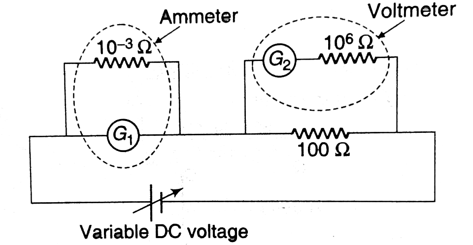
Draw the circuit for experimental verfication of Ohm's law using a source of variable DC voltage, a main resistance of 100(Ω), two galvanometers and two resistances of values 106Ω and 10−3 respectively. Clearly show the positions of the voltmeter and the ammeter.
 .
.
Topper's Solved these Questions
- EXPERIMENTSBOOK - DC PANDEYCHAPTER - EXPERIMENTSEXERCISE - Exercise 3.1
2 Videos
- EXPERIMENTSBOOK - DC PANDEYCHAPTER - EXPERIMENTSEXERCISE - Exercise 3.2
2 Videos
- ELECTROSTATICSBOOK - DC PANDEYCHAPTER - ELECTROSTATICSEXERCISE - Integer
17 Videos
- FLUID MECHANICSBOOK - DC PANDEYCHAPTER - FLUID MECHANICSEXERCISE - Medical entranes gallery
49 Videos
Similar Questions
Draw the circuit for experimental verification of Ohm's law using a source of variable DC voltage, a main resistance of 100Ω, two galvanometers and two resistances of value 106Ω and 10−3Ω respectively. Clearly show the positions of the voltmeter and the ammeter.
View SolutionDraw the circuit diagram to verify Ohm's Law with the help of a main resistance of 100Ω and tow galvanometer of resistance 106Ωand10−3Ω and a source of varying emf.
Show the correct positions of volmeter and ammeter.
View Solution
Knowledge Check
A voltmeter has a resistance of 100Ω and measures 10 V. How can it be used to meaure 50 V ?
A40Ω in seriesB40Ω in parallelC400Ω in seriesD400Ω in parlllelThe equivalent resistances of a series combination of two resistances is XΩ. If the resistances are of 10Ωand40Ω respectively. The value of X will be:
A10ΩB20ΩC50ΩD40ΩA voltmeter of range 0−10V and resistance 200Ωcannot be used as an ammeter, whose range is
A0−500mAB0−250mAC0−100mAD0−25mA
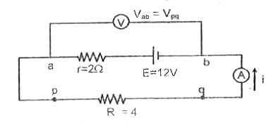
The figure shows a source (a battery) with an emf E of 12 V with an internal resistance r of 2Ω and an external resistance of 4Ω is added to complete the circuit. What are the voltmeter and ammeter readings

View SolutionAn experiment is performed to calculate the value of an unknown resistance R of range K Ω by using a battery of variable potential difference, a voltmeter of resistance 106Ω and an ammeter of resistance 10−3Ω. Choose the circuit diagram which indicates correctly the position of ammeter and voltmeter so that percentage error in calculation of R is minimum
View SolutionIn an ammeter, 10% of the main current is passing through galvanometer, it the galvanometer is shunted with a 10 Ω resistance. What is the resistance of the galvanometer ?
View SolutionThe equivalent resistance of a series combination of two resistances is X ohm. If the resistance are of 10 ohm and 40 ohm respectively, the value of X will be
View SolutionA galvanometer of resistance 100 Ω is converted to a voltmeter of range 10 y by connecting a resistance of 10 Ω. The resistance required to convert the same galvanometer to an ammeter of range 1 A is
View Solution
