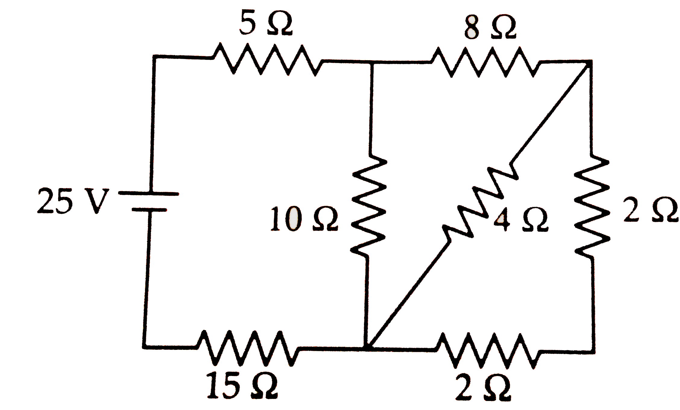
For the circuit shown in figure, determine the voltage across 4Ω resistors in volt ?

The correct Answer is:2
Step by step video & image solution for For the circuit shown in figure, determine the voltage across 4Omega resistors in volt ? by Physics experts to help you in doubts & scoring excellent marks in Class 12 exams.
Updated on:21/07/2023Topper's Solved these Questions
- CURRENT ELECTRICITYBOOK - AAKASH SERIESCHAPTER - CURRENT ELECTRICITYEXERCISE - LECTURE SHEET (EXERCISE-V LEVEL - I (MAIN) (Straight Objective Type Questions))
6 Videos
- CURRENT ELECTRICITYBOOK - AAKASH SERIESCHAPTER - CURRENT ELECTRICITYEXERCISE - LECTURE SHEET (EXERCISE-V LEVEL-II (ADVANCED) (Straight Objective Type Questions))
5 Videos
- CURRENT ELECTRICITYBOOK - AAKASH SERIESCHAPTER - CURRENT ELECTRICITYEXERCISE - LECTURE SHEET (EXERCISE-IV LEVEL- II (ADVANCED) (Linked Comprehension Type Questions))
3 Videos
- CURRENT ELECTRICITYBOOK - AAKASH SERIESCHAPTER - CURRENT ELECTRICITYEXERCISE - PROBLEMS (LEVEL-II)
27 Videos
- DUAL NATURE OF RADIATION AND MATTERBOOK - AAKASH SERIESCHAPTER - DUAL NATURE OF RADIATION AND MATTEREXERCISE - PRACTICE EXERCISEX
42 Videos
Similar Questions
Knowledge Check
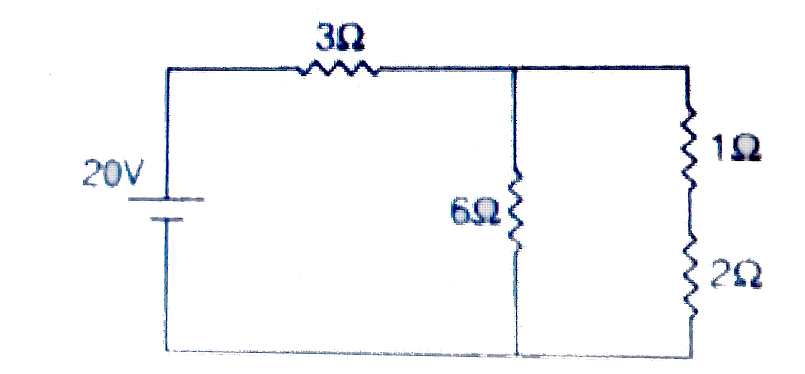
For the circuit shown in the figure, the current in the 4Ω resistor is
 A0.5AB0.25AC1AD1.5A
In the circuit shown in figure potential difference across
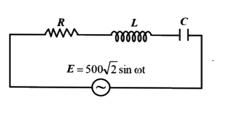
View SolutionIn the series L−C−R circuit shown in the figure, the rms voltage across the resistor and inductor are 400 V and 700 V respectively. If the applied voltage is E=500√2sin(ωt), then the peak voltage across the capacitor is
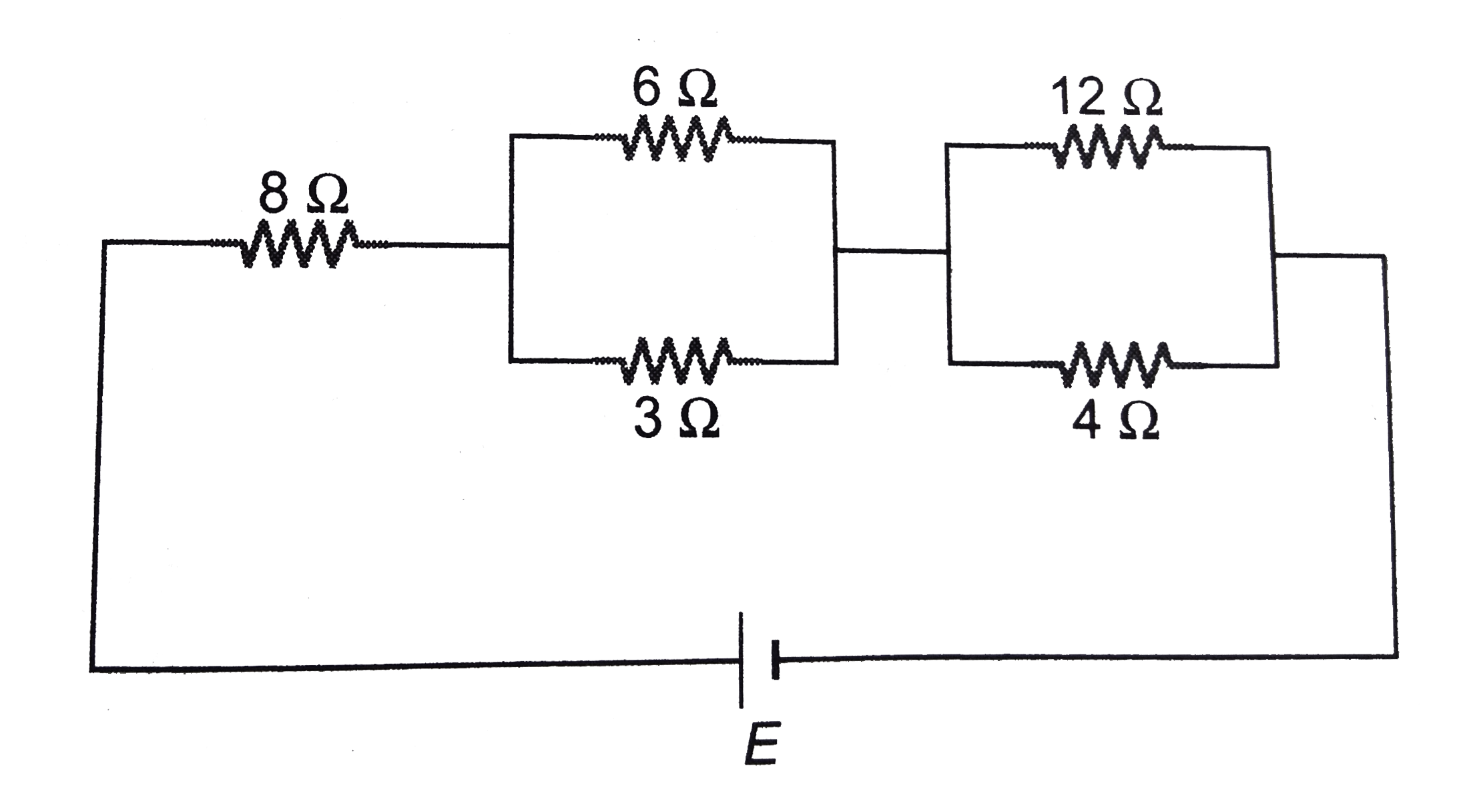
View SolutionIn the circuit shown in figure potential differences across 6Ω resistance is 4 volt. Find V and i values across each resistance. Also find emf E of the applied battery.
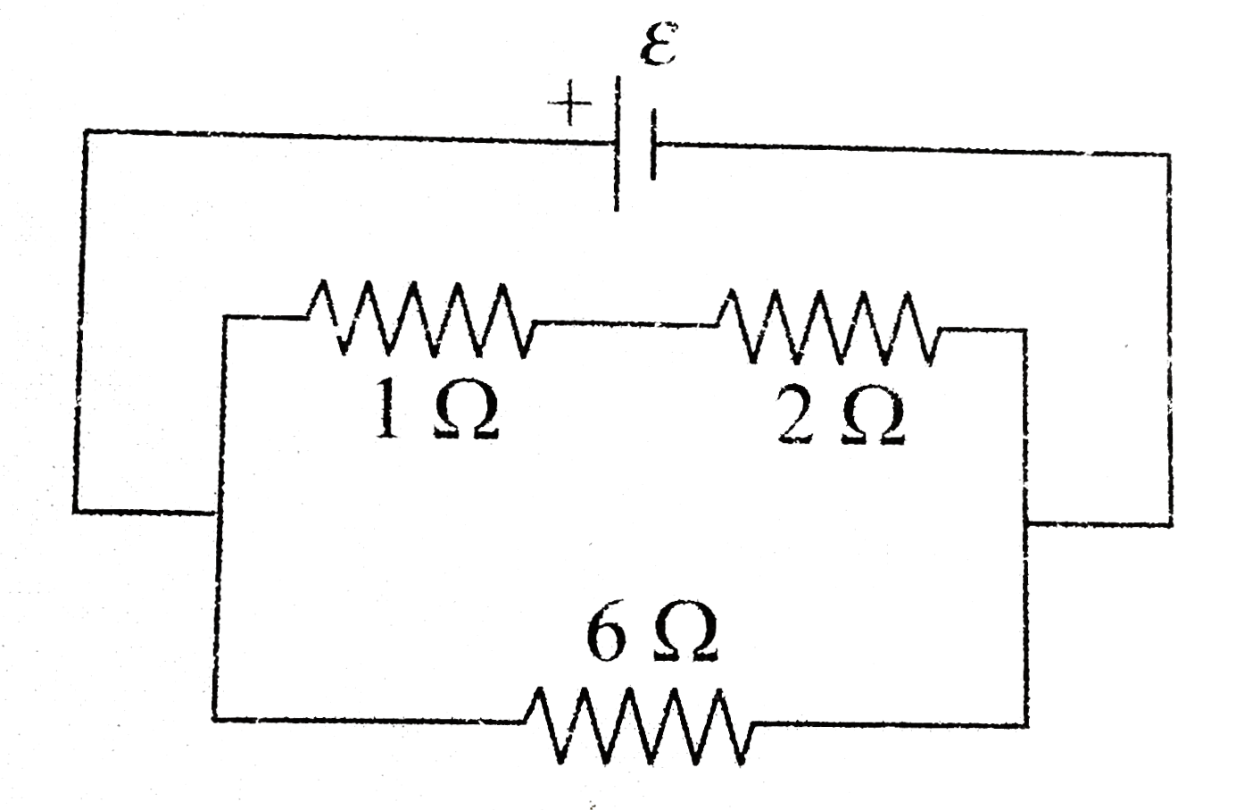
View SolutionIn the circuit shown in fig the voltage across the 2 Ω resistor is 12V. What is the emf of the battery and the current thorugh the 6 Ω resistor?
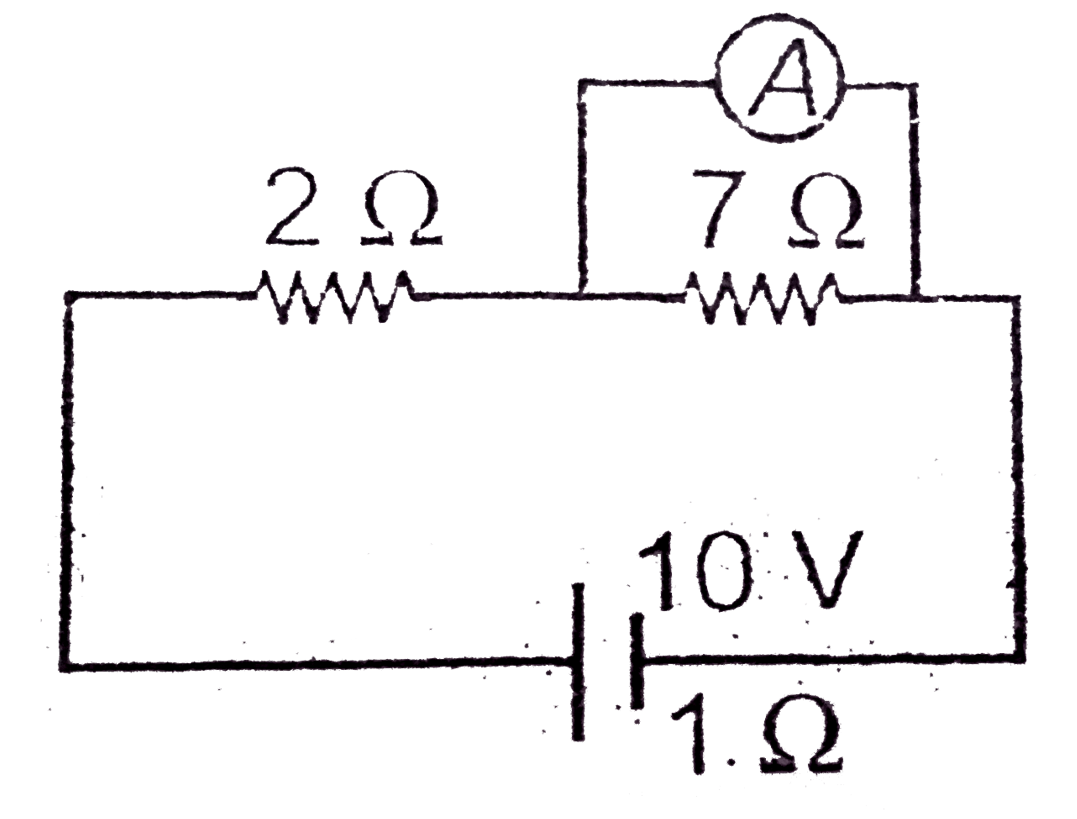
View SolutionIn the situation shown in figure , an ideal ammeter is connected across 7Ωresistors. Select the correct statement from the following
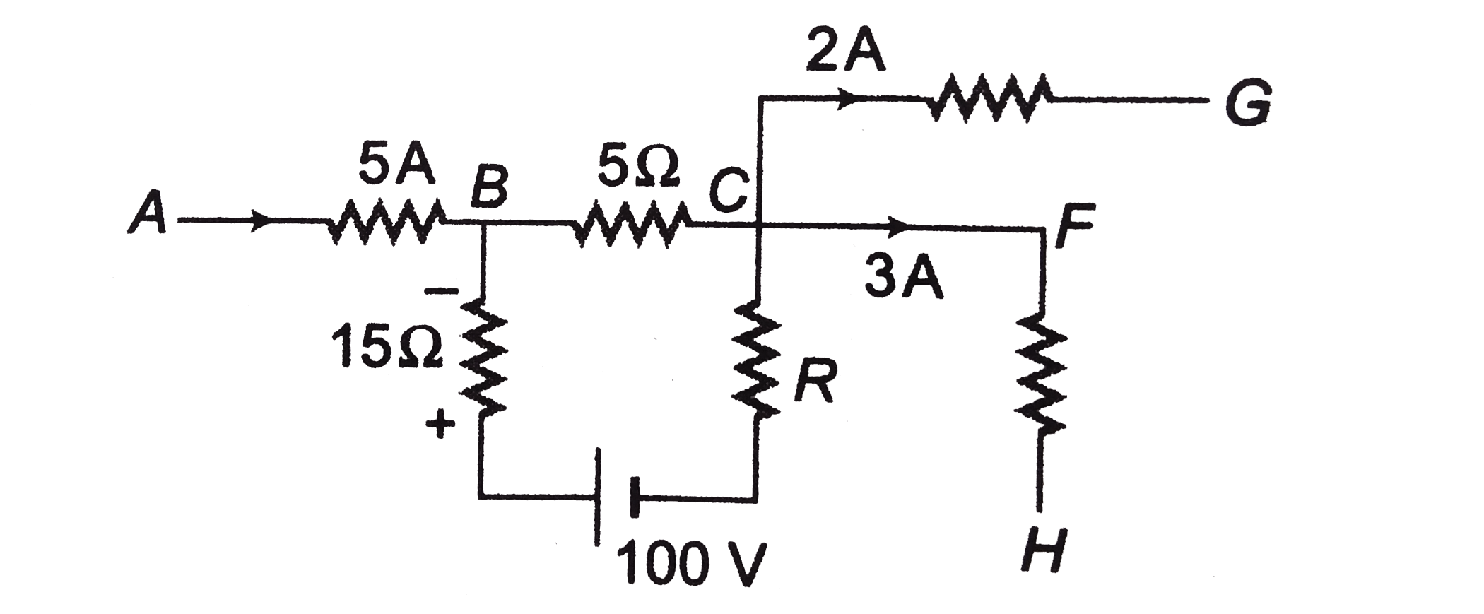
View SolutionIn the circuit shown the voltage drop across the 15Ω resistor is 30V having the polarity as indicated. The ratio of potential difference across 5Ω and resistance R is
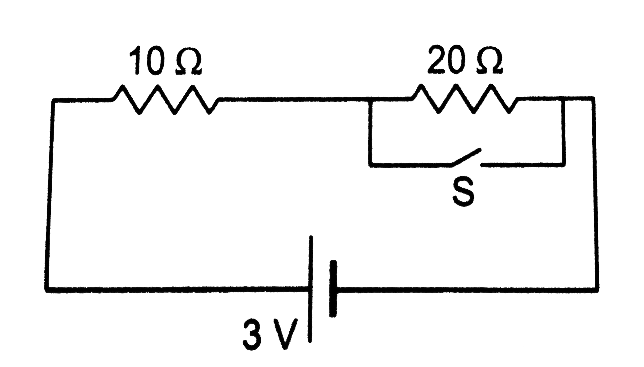
View SolutionConsider the circuit shown in figure.Find the current through the10(Ω)resistor when the switch S is (a)open (b)closed .
View Solution

