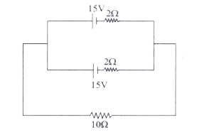
For the circuit shown in the figure what is the potential difference across the external resistance ?
A
10V
B
7.5 V
C
15 V
D
30V
Text Solution
The correct Answer is:C
Voltage is unaffected in parallel combination
|
Topper's Solved these Questions
- SOURCES OF ELECTRIC CURRENTBOOK - CENGAGE PHYSICSCHAPTER - SOURCES OF ELECTRIC CURRENTEXERCISE - OLYMPIAD AND NTSE LEVEL EXERCISES
10 Videos
- SOURCES OF ELECTRIC CURRENTBOOK - CENGAGE PHYSICSCHAPTER - SOURCES OF ELECTRIC CURRENTEXERCISE - MANDATORY EXERCISE (Exercise Set IV)
9 Videos
- REFRACTION OF LIGHT BOOK - CENGAGE PHYSICSCHAPTER - REFRACTION OF LIGHT EXERCISE - OLYMPIAD AND NSE LEVEL EXCERCISES
10 Videos
- STATIC ELECTRICITYBOOK - CENGAGE PHYSICSCHAPTER - STATIC ELECTRICITYEXERCISE - OLYMPIAD AND NTSE LEVEL EXERCISES
10 Videos
Similar Questions
Knowledge Check
In the circuit shown in the figure, the potential difference across the 4.5μF capacitor is
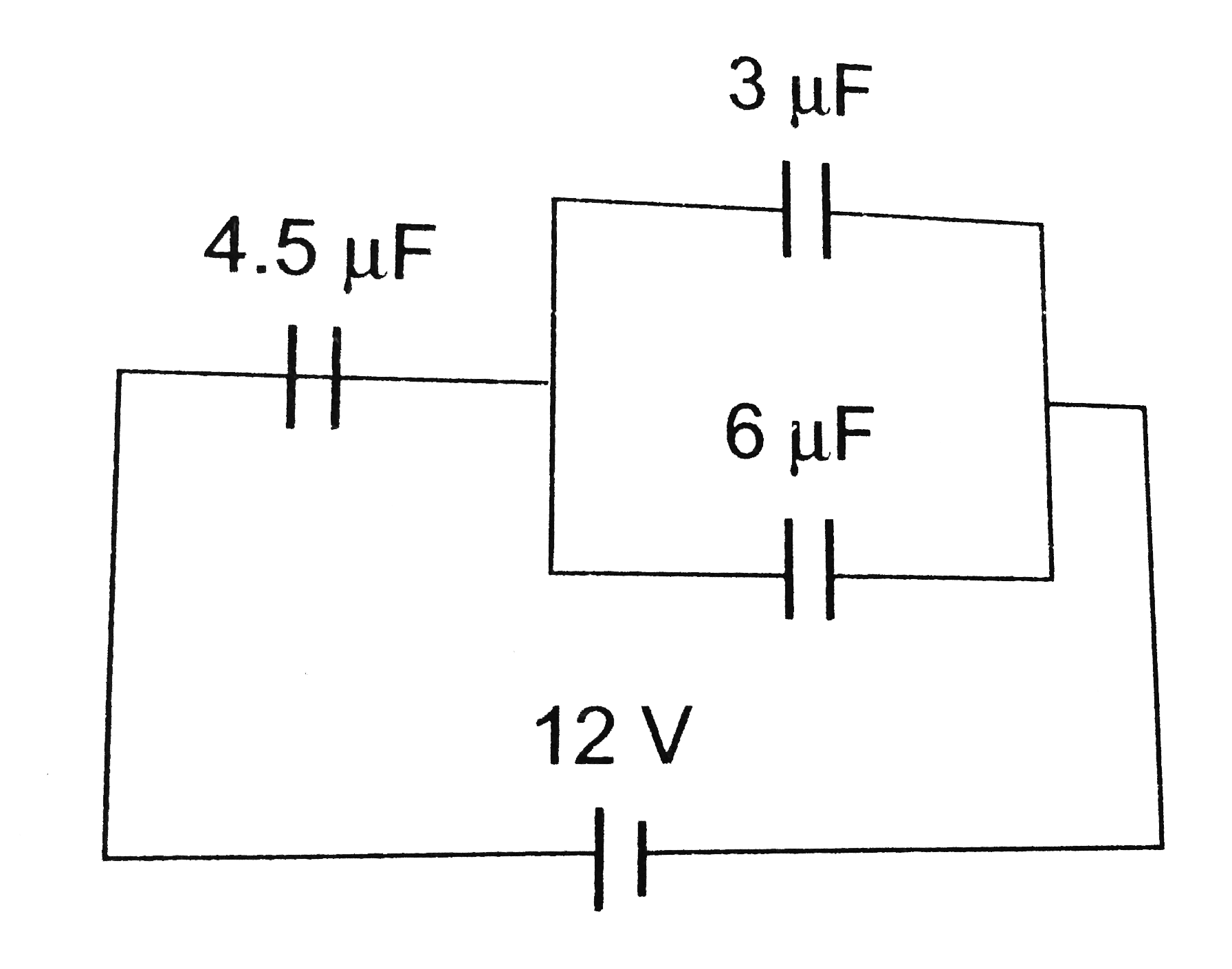 A83voltsB4 voltsC6 voltsD8 volts
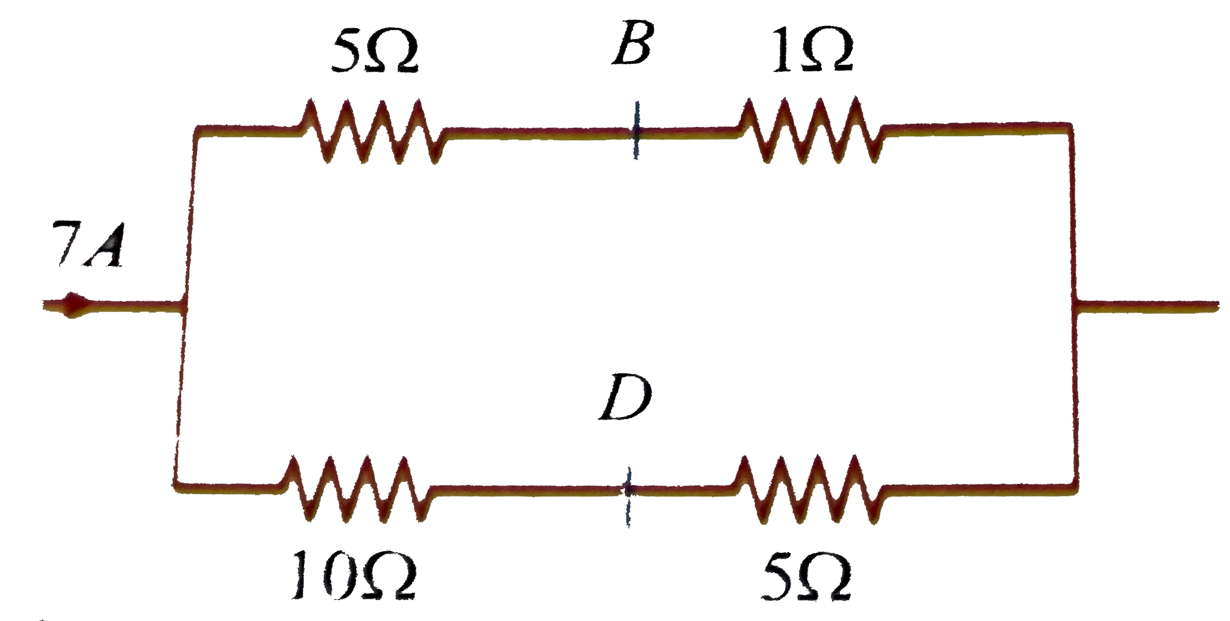
A current of 7 A flows through the circuit as shown in the figure the potential difference across points B and D isA5VB3VC10VD7VIn the shown circuit, what is the potential difference across A and B
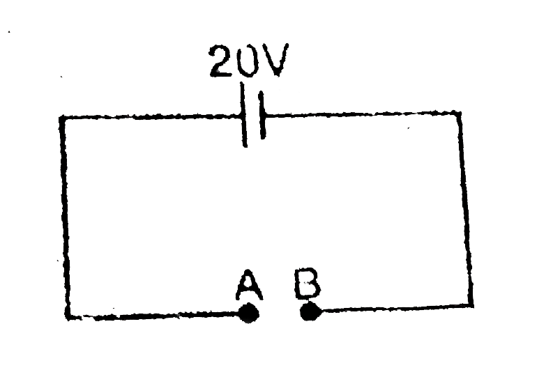 A50 VB45 VC30 VD20 V
In the circuit shown in the following the potential difference across the 3μF capacitor is
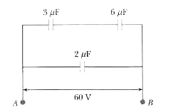
View SolutionIn the shown circuit, what is the potential difference across A and B

View SolutionIn the electrical network shown in the figure, What will be the potential difference (in volt) across 3Ω resistance ?
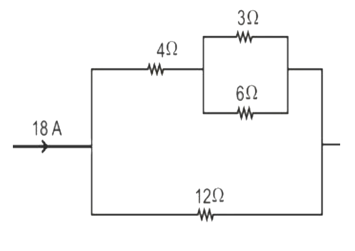
View SolutionIn the electrical network shown in the figure, What will be the potential difference (in volt) across 3Ω resistance ?

View SolutionIn the circuit shown, rms circuit is 11 A . The potential difference across the inductor is
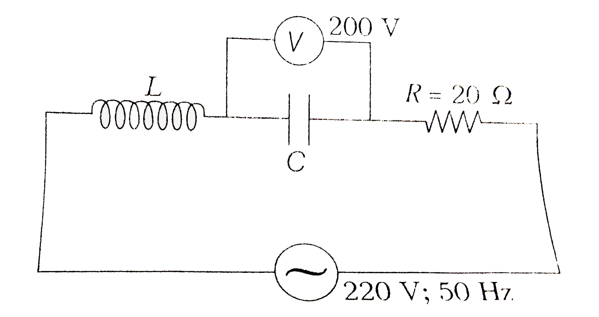
View Solution

