In a series LCR circuit, voltage drop axross L can be more than applied voltage (True/false).
True, voltage across inductor is given by
VLv=IvXL=EvXL√R2+(XL−X2C)
for certain values of R, XLandXC,XL can be grater than Z=√R2+(XL−X2C). In that case VLv can be greater than Ev.
Topper's Solved these Questions
- ALTERNATING CURRENTBOOK - CENGAGE PHYSICSCHAPTER - ALTERNATING CURRENTEXERCISE - Exercises Subjective
15 Videos
- ALTERNATING CURRENTBOOK - CENGAGE PHYSICSCHAPTER - ALTERNATING CURRENTEXERCISE - Exercises Single Correct
63 Videos
- ALTERNATING CURRENTBOOK - CENGAGE PHYSICSCHAPTER - ALTERNATING CURRENTEXERCISE - Solved Examples
6 Videos
- OSCILLATIONSBOOK - CENGAGE PHYSICSCHAPTER - OSCILLATIONSEXERCISE - QUESTION BANK
39 Videos
- ATOMIC PHYSICSBOOK - CENGAGE PHYSICSCHAPTER - ATOMIC PHYSICSEXERCISE - ddp.4.3
15 Videos
Similar Questions
In a series LCR circuit, the voltages across an inductor, a capacitor and a resistor are 30 V, 30 V, 60 V respectively. What is the phase difference between the applied voltage and the current in the circuit ?
View SolutionIn a series LCR circuit, the voltage across an inductor, a capacitor and a resistor are 20 V, 20 V and 40 V, respectively. What is the phase difference between the applied voltage and the current in the circuit ?
View Solution
Knowledge Check
In a series LCR circuit, the voltage across the inductance and capacitance are not
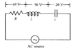
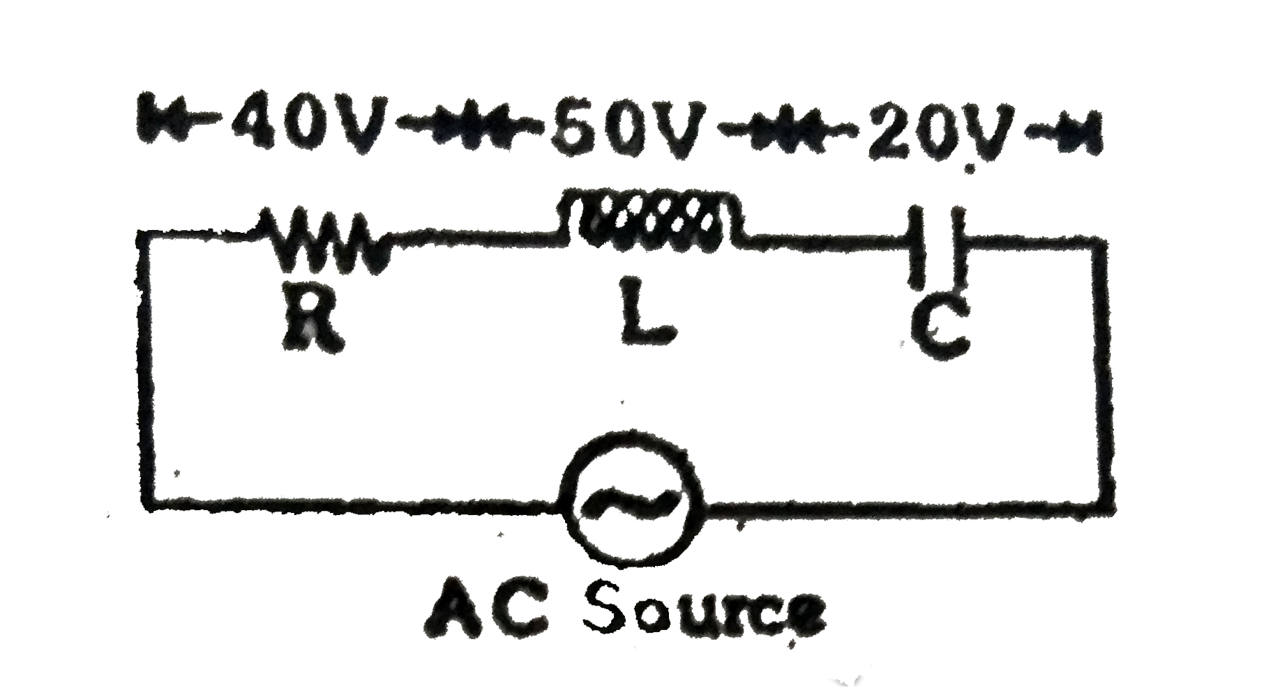
Aout of phase with voltage across resistance by 90∘Bequal in magnitude at resonanceCout of phase with each other by 180∘Din phase with the source voltageIn series LCR circuit, the voltages across R, L and C shown in figure. The voltage of applied source is
 A110 voltB10 voltC50 voltD70 volt
In series LCR circuit, the voltages across R, L and C are shown in the figure. The voltage of applied source
 A110 VB10 voltC50 voltD70 volt
STATEMENT-1: In a series LCR circuit at resonance, the voltage across the capacitor or inductor may be more than the applied voltage.
STATEMENT-2: At resonance in a series LCR circuit, the voltages across inductor and capacitor are out of phase.
View SolutionIn a series LR circuit, the voltage drop across inductor is 8 volt and across resistor is 6 volt. Then voltage applied and power factor of circuit respectively are:
View SolutionIn series LCR circuit, the phase angle between supply voltage and current is
View SolutionIn series LCR AC circuit, the voltage of the source at any instant is equal to
View SolutionVoltage across an inductor, capacitor and a resistor is 30 V, 0 V and 60 V respectively in a series LCR circuit then the phase difference between the applied voltage and applied current will be:
View Solution
