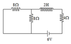
In an LR-circuit, time constant is that time in which current grows from zero to the value (where I0 is the steady state current)
0.63I0
0.50I0
0.37I0
I0
The correct Answer is:A
To solve the problem regarding the time constant in an LR circuit, we can follow these steps:
1. Understanding the LR Circuit:
An LR circuit consists of an inductor (L) and a resistor (R) connected in series. When a voltage is applied, the current (I) in the circuit does not immediately reach its maximum value (steady state current, I0) but increases gradually.
2. Current Growth Equation:
The current at any time t in an LR circuit is given by the formula:
I(t)=I0(1−e−RLt)
where:
- I(t) is the current at time t,
- I0 is the steady-state current,
- R is the resistance,
- L is the inductance,
- e is the base of the natural logarithm.
3. Defining the Time Constant:
The time constant τ for an LR circuit is defined as:
τ=LR
This is the time required for the current to reach approximately 63.2% of its maximum value (steady state).
4. Finding Current at Time Constant:
To find the current at the time constant τ, we substitute t=τ into the current equation:
I(τ)=I0(1−e−RL⋅LR)
Simplifying this gives:
I(τ)=I0(1−e−1)
5. Calculating e−1:
The value of e−1 is approximately 0.3679. Therefore,
I(τ)=I0(1−0.3679)≈I0⋅0.6321
This means that at the time constant τ, the current reaches about 63.2% of its steady-state value I0.
6. Conclusion:
The time constant τ is the time it takes for the current to grow from zero to approximately 0.6321I0 in an LR circuit.
Final Answer:
The time constant τ in an LR circuit is defined as τ=LR, and at this time, the current reaches approximately 0.6321I0.
---
An LR circuit consists of an inductor (L) and a resistor (R) connected in series. When a voltage is applied, the current (I) in the circuit does not immediately reach its maximum value (steady state current, I0) but increases gradually.
The current at any time t in an LR circuit is given by the formula:
I(t)=I0(1−e−RLt)
where:
- I(t) is the current at time t,
- I0 is the steady-state current,
- R is the resistance,
- L is the inductance,
- e is the base of the natural logarithm.
The time constant τ for an LR circuit is defined as:
τ=LR
This is the time required for the current to reach approximately 63.2% of its maximum value (steady state).
To find the current at the time constant τ, we substitute t=τ into the current equation:
I(τ)=I0(1−e−RL⋅LR)
Simplifying this gives:
I(τ)=I0(1−e−1)
The value of e−1 is approximately 0.3679. Therefore,
I(τ)=I0(1−0.3679)≈I0⋅0.6321
This means that at the time constant τ, the current reaches about 63.2% of its steady-state value I0.
The time constant τ is the time it takes for the current to grow from zero to approximately 0.6321I0 in an LR circuit.
The time constant τ in an LR circuit is defined as τ=LR, and at this time, the current reaches approximately 0.6321I0.
Topper's Solved these Questions
- BOOK - A2ZCHAPTER - ELECTROMAGNETIC INDUCTIONEXERCISE - Applications Of Emi58videos
ELECTROMAGNETIC INDUCTION
- BOOK - A2ZCHAPTER - ELECTROMAGNETIC INDUCTIONEXERCISE - Problems On Mixed Concepts37videos
ELECTROMAGNETIC INDUCTION
- BOOK - A2ZCHAPTER - ELECTROMAGNETIC INDUCTIONEXERCISE - Motional And Rotational Emf95videos
ELECTROMAGNETIC INDUCTION
- BOOK - A2ZCHAPTER - ELECTRIC POTENTIAL & CAPACITANCEEXERCISE - Section D - Chapter End Test29videos
ELECTRIC POTENTIAL & CAPACITANCE
- BOOK - A2ZCHAPTER - ELECTROMAGNETIC WAVES AND COMMUNICATION SYSTEM EXERCISE - Section D - Chapter End Test30videos
ELECTROMAGNETIC WAVES AND COMMUNICATION SYSTEM
Similar Questions
Knowledge Check
- Question 1 - Select One
Time constant of LR circuit will be
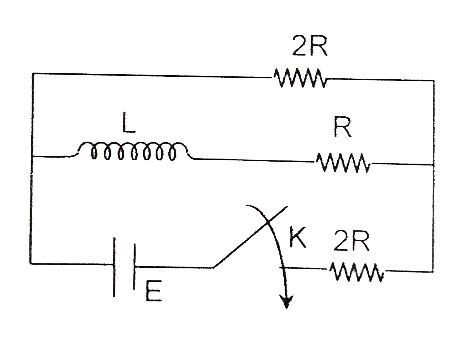 ALRB2LRCL2RDNone of these
 - Question 2 - Select One
In the circuit shown in the figure, in steady state:

The current drawn from the battery isA2AB3AC4AD1A - Question 3 - Select One
In adjacent circuit, switch S is closed at t = 0. The time at which current in the circuit becomes half of the steady current is
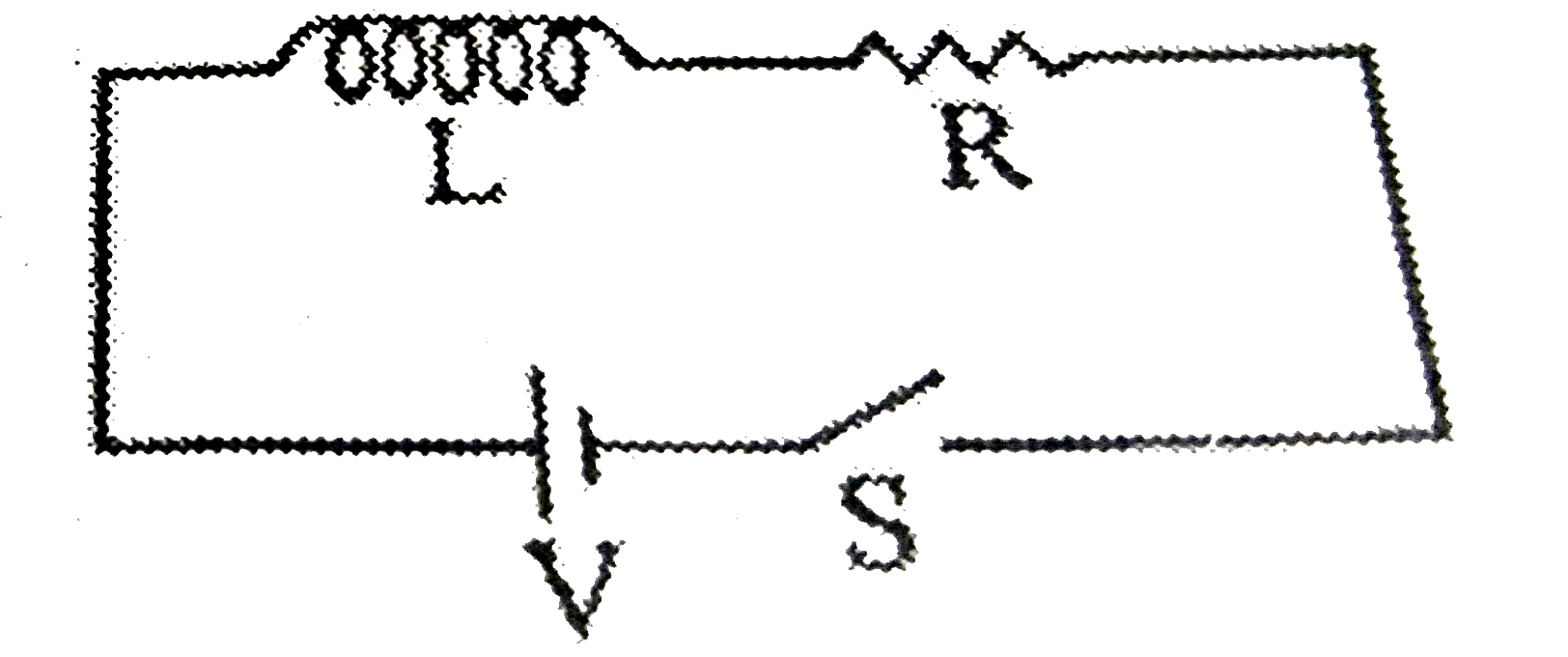 Aτln2Bln2τC2τln2Dτ2ln2
In the given circuit, what is the current I (in A) drawn from battery at time t = 0.
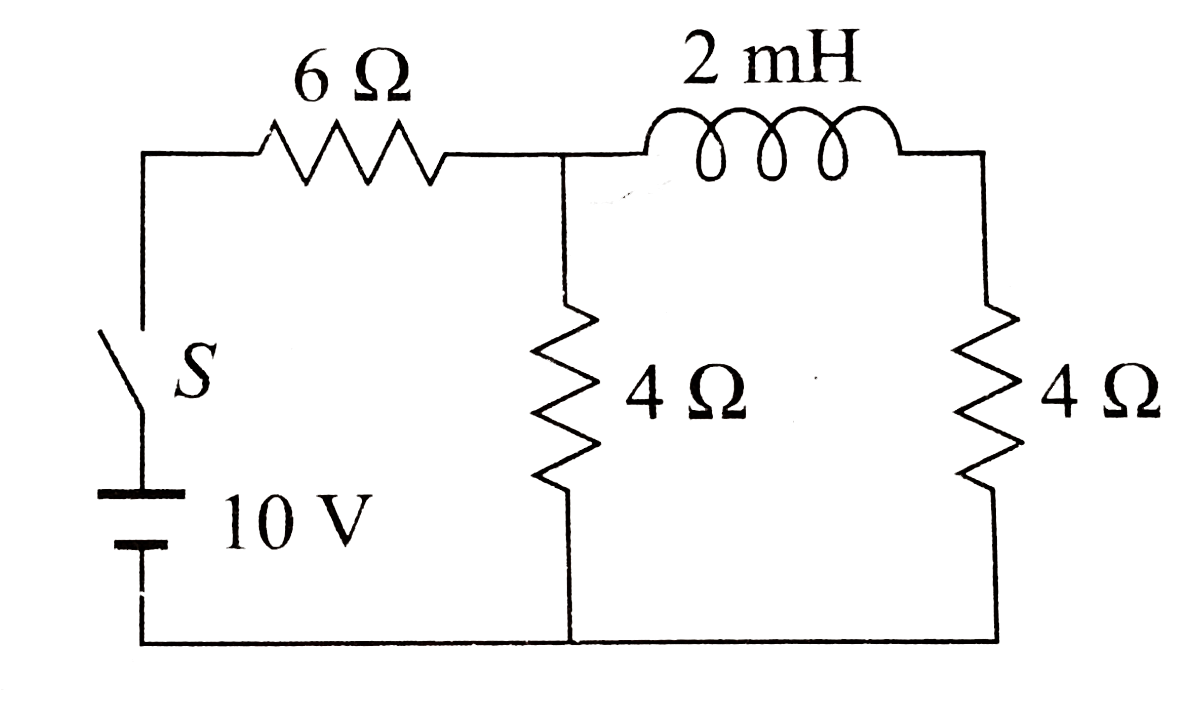 View Solution
During current growth in an L-R circuit the time constant is the time in which the magnitude of current becomes
View SolutionThe time constant of an LR circuit respresents the time in which the current in the circuit
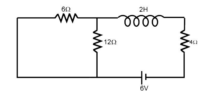
View SolutionIn the circuit shown in fig.. Time constant and steady state current will be
 View Solution
In the Ac circuit, the current is expressed as / = 100 sin 200πt. In this circuit the current rises from zero to peak value in time
View Solution


