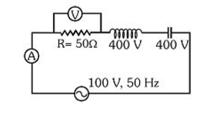
In anLCR circuit .
current always lags behind voltage if
current and voltage are always in phase
current in the voltage if ω>1√LC
current lags behind the voltage ifω<1√LC
The correct Answer is:C
To solve the problem regarding the behavior of current and voltage in an LCR circuit, we will analyze the relationships between them based on the given conditions.
1. Understanding the LCR Circuit:
- An LCR circuit consists of an inductor (L), a capacitor (C), and a resistor (R) connected in series. In an AC circuit, the behavior of the current and voltage across these components can vary based on the frequency of the source.
Hint: Recall the definitions of inductive reactance (XL = ωL) and capacitive reactance (XC = 1/ωC).
2. Phasor Representation:
- In an LCR circuit, the current (I) is the same through all components since they are in series. The voltage across the inductor (VL) leads the current by 90 degrees, while the voltage across the capacitor (VC) lags the current by 90 degrees. The voltage across the resistor (VR) is in phase with the current.
Hint: Draw a phasor diagram to visualize the phase relationships between I, VL, VC, and VR.
3. Condition of Resonance:
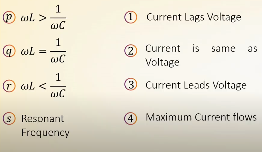
- At resonance, the inductive reactance (XL) equals the capacitive reactance (XC), which means that the net reactance is zero. This occurs at the resonant frequency (ω0 = 1/√(LC)).
Hint: Remember that at resonance, the total impedance is minimized, and the circuit behaves purely resistively.
4. Analyzing Phase Relationships:
- If VL > VC, the net voltage (V) leads the current (I). Conversely, if VC > VL, the net voltage lags behind the current. This indicates that the phase relationship between current and voltage can change depending on the values of L and C.
Hint: Consider how the frequency (ω) affects the values of XL and XC.
5. Determining Conditions for Current Leading or Lagging:
- If the frequency is such that ω < 1/√(LC), then XL < XC, and the current leads the voltage. If ω > 1/√(LC), then XL > XC, and the current lags behind the voltage.
Hint: Use the inequality to determine the leading or lagging condition based on the frequency.
6. Conclusion:
- Based on the analysis, we can conclude that:
- Current can lead or lag behind the voltage depending on the frequency of the source.
- Therefore, the statement "current always lags behind voltage" is incorrect.
- The correct option is that current lags behind voltage when the frequency is greater than the resonant frequency.
Final Answer: The correct option is that current lags behind the voltage when ω > 1/√(LC).
- An LCR circuit consists of an inductor (L), a capacitor (C), and a resistor (R) connected in series. In an AC circuit, the behavior of the current and voltage across these components can vary based on the frequency of the source.
- In an LCR circuit, the current (I) is the same through all components since they are in series. The voltage across the inductor (VL) leads the current by 90 degrees, while the voltage across the capacitor (VC) lags the current by 90 degrees. The voltage across the resistor (VR) is in phase with the current.
- At resonance, the inductive reactance (XL) equals the capacitive reactance (XC), which means that the net reactance is zero. This occurs at the resonant frequency (ω0 = 1/√(LC)).
- If VL > VC, the net voltage (V) leads the current (I). Conversely, if VC > VL, the net voltage lags behind the current. This indicates that the phase relationship between current and voltage can change depending on the values of L and C.
- If the frequency is such that ω < 1/√(LC), then XL < XC, and the current leads the voltage. If ω > 1/√(LC), then XL > XC, and the current lags behind the voltage.
- Based on the analysis, we can conclude that:
- Current can lead or lag behind the voltage depending on the frequency of the source.
- Therefore, the statement "current always lags behind voltage" is incorrect.
- The correct option is that current lags behind voltage when the frequency is greater than the resonant frequency.
Topper's Solved these Questions
Similar Questions
Knowledge Check
In LCR circuit during resonance
Apower factor is zeroBpower factor is oneCpower developed acrtoss resistance is zeroDpower developed across capacitance is zeroIn LCR circuit as shown in figure
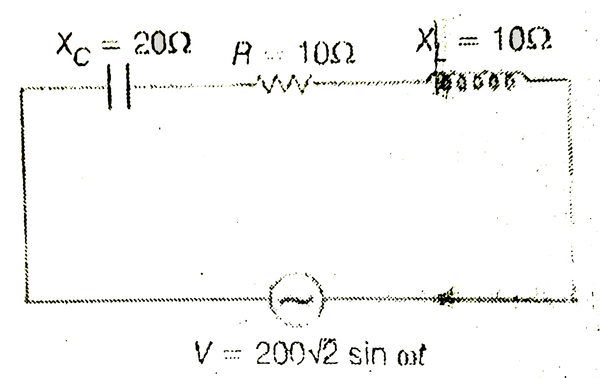 Acurrent will lead the voltageBrms value of current is 20ACpower factor of circuit is 1√2Dvoltage drop across resistance is 100V
Reduction of resonant frequency in LCR circuit with a generator is done by:
ARemoving dielectric in a capacitorBRemoving iron core of the inductorCRemoving generator frequencyDAdding another capacitor in parallel to
When the frequency of AC is doubled, the impedance of an LCR, circuit is
View SolutionIn LCR - circuit if resistance increases, quality factor
View SolutionIn LCR circuit shown in figure, then choose incorrect option:
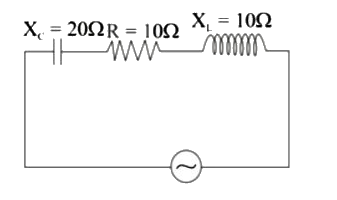
View SolutionAssertion (A) : Quality factor of a series LCR circuit is Q=1R√LC
Reason (R) : As bandwidth decreases, Q increases in a resonant LCR circuit.
View SolutionFor an LCR circuit,
View Solution

