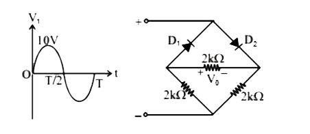
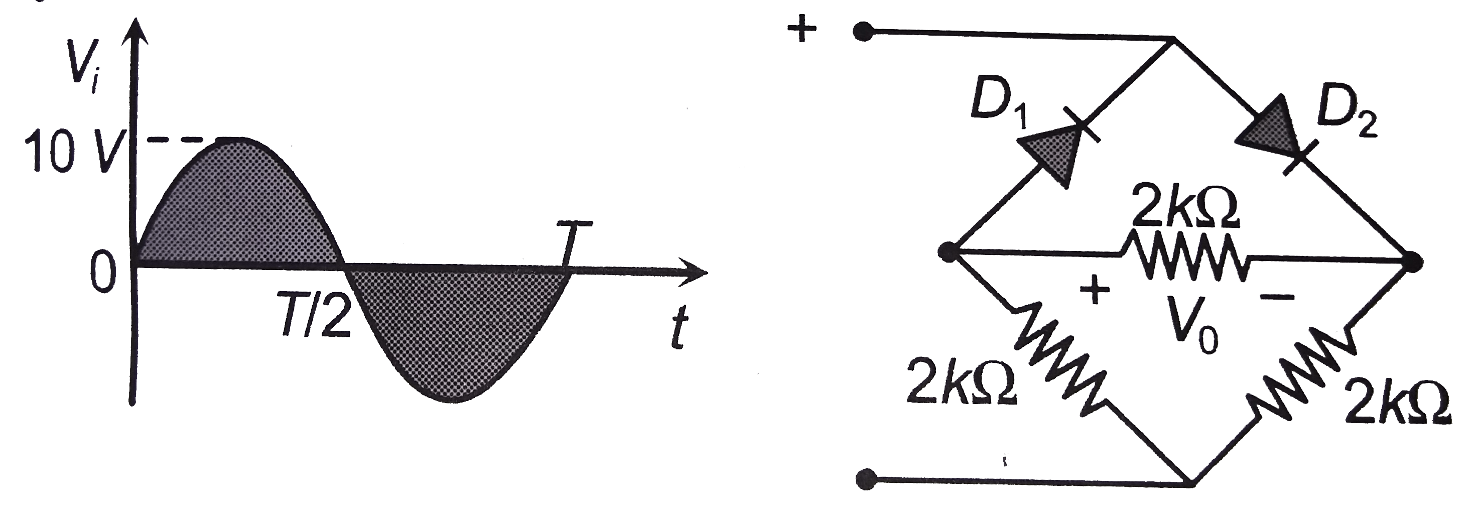
In circuit shown in figure, determine the output waveform, output d.c. level of 'V'0 :
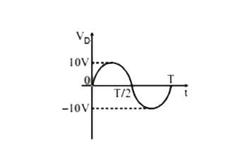
A
B
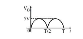
C
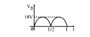
D
none of these
Video Solution
Text Solution
The correct Answer is:B
For the positive half cycle of input the resulting network is shown in figure (b). Diode D1 is in ''off'' state and D2 is in ''on'' state. Circuit has been redrawn in figure (c ). It is clear that
V0=12V1
or V0max=12Vimax=12(10V)=5V

During negative half cycle the roles of diodes D1 and D2 will be interchanged and V0 will appear as shown in figure (d).
For full - wave rectification
Vd.c=0.636Vm=0.636×5V=3.18V
|
Topper's Solved these Questions
Similar Questions
Knowledge Check
In the circuit shown in figure the maximum output voltage V0 is
 A0VB5VC10VD5√2V
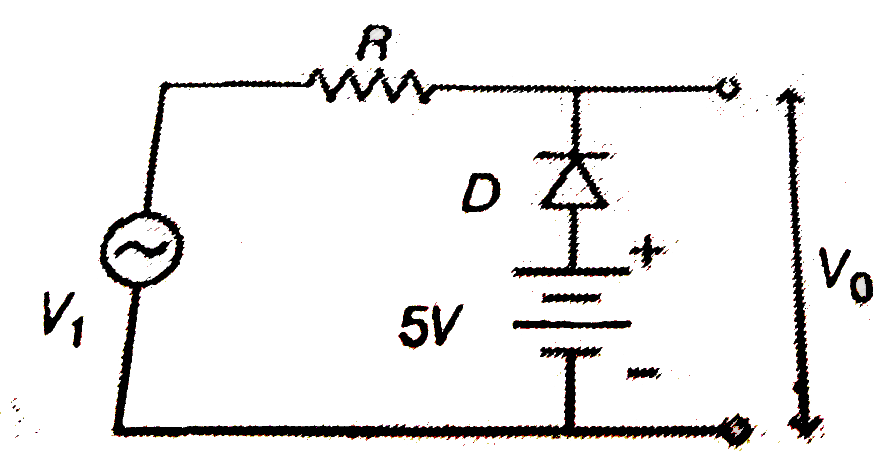
In the figure, D is an ideal diode and an alternating voltage of peak value 10 volts si connected as input V1. Which of the following figures represents the correct waveform of output voltage V0 ?
 A
A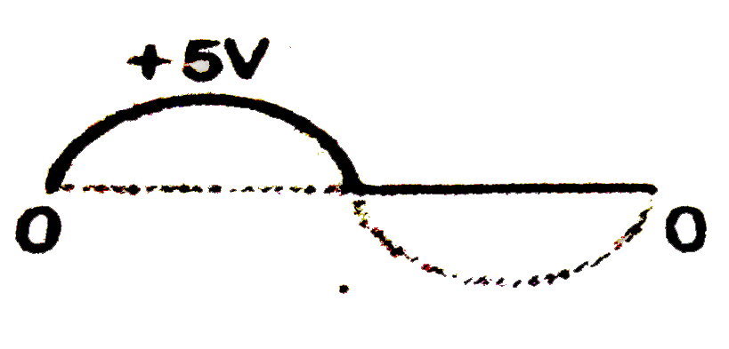 B
B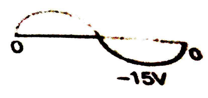 C
C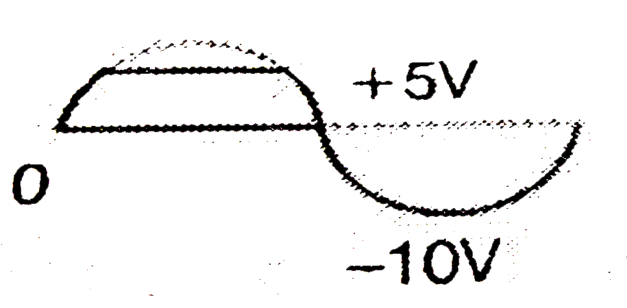 D
D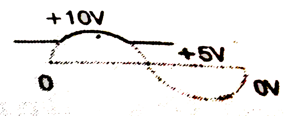
In the figure, the input waveform is converted into the output waveform by a device X. The devise X is a/an
 AamplifierBhalf wave rectifierCfull wave rectifierDoscillator
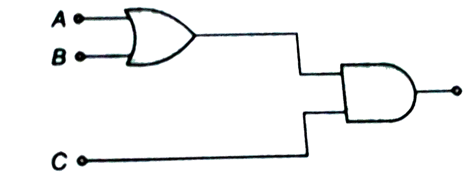
To get an output 1 from the circuit shown in figure the input must be :

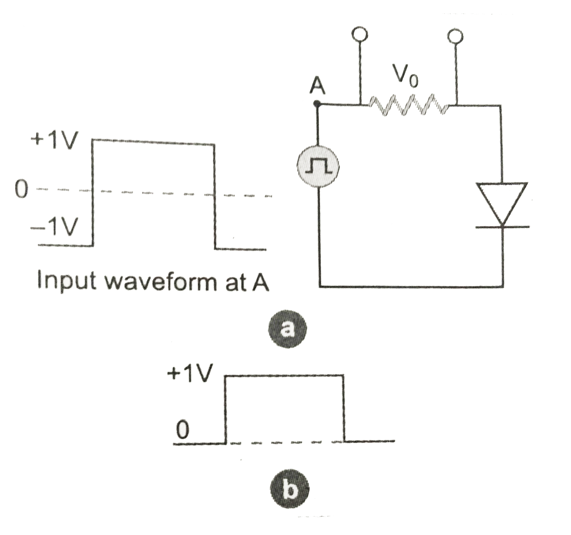
View SolutionDraw the output waveform across the resistor (Fig.)
View SolutionTo get an output 1 from the circuit shown in the figure, the input must be
View SolutionTo get an output 1 from the circuit shown in the figure, the input must be

View SolutionTo get an output 1 from the circuit shown in the figure, the input must be

View Solution
