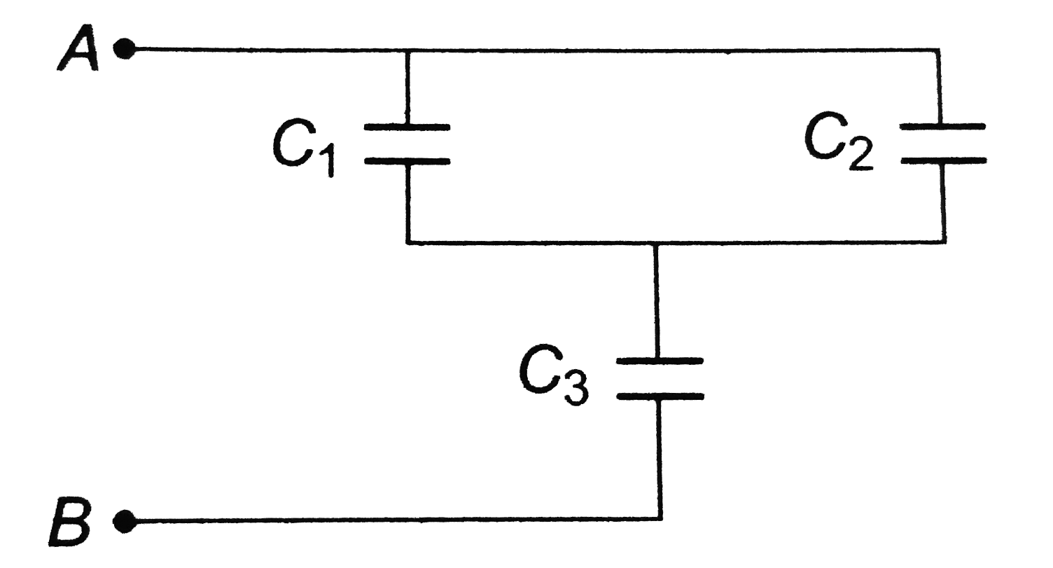
In fig. C1=20μF,C2=30μFandC3=15μF and the insulated plate of C1 is at a potential of 90 V, one plate of C3 being earthed. What is the potential difference between th plates of C2 three capacitors being connected in series ?
Step by step video & image solution for In fig. C_(1) = 20 muF, C_(2) = 30 muF and C_(3) = 15 muF and the insulated plate of C_(1) is at a potential of 90 V, one plate of C_(3) being earthed. What is the potential difference between th plates of C_(2) three capacitors being connected in series ? by Physics experts to help you in doubts & scoring excellent marks in Class 12 exams.
Updated on:21/07/2023Topper's Solved these Questions
- CAPACITORSBOOK - SL ARORACHAPTER - CAPACITORSEXERCISE - Problem From Competitive Examinations
17 Videos
- CAPACITORSBOOK - SL ARORACHAPTER - CAPACITORSEXERCISE - problem for self practive
65 Videos
- ATOMS, NUCLEI AND MOLECULESBOOK - SL ARORACHAPTER - ATOMS, NUCLEI AND MOLECULESEXERCISE - Problems For Self Practice
87 Videos
- CHEMICAL EFFECT OF CURRENTBOOK - SL ARORACHAPTER - CHEMICAL EFFECT OF CURRENTEXERCISE - TYPE-B
5 Videos
Similar Questions
A charge of 20 muC is placed on the positive plante of on isolated parailel - plate capacitor of capacitance 10μF calculate the potential difference developed between the plates .
View SolutionIn, given C1=3μF,C2=5μF,C3=9μF, and C4=13μF. What is the potential differnce between points A and B?
 .
.
View Solution
Knowledge Check
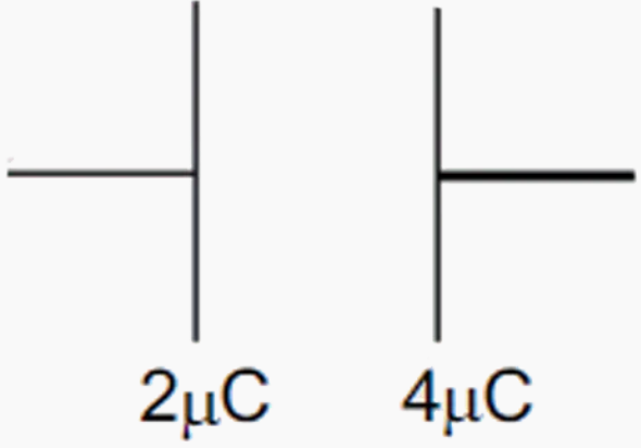
In a parallel plate capacitor of capacitor 1μF two plates are given charges 2μC and 4μC the potential difference between the plates of the capacitor is
 A2 voltB1 voltC4 voltD3 volt
In an isolated parallel plate capacitor of capacitance C, the plates have charge Q1 and Q2. The potential difference between the plates is
AQ1+Q22CBQ1−Q22CCQ12CD−Q22CA capacitor of 6μF is charged to such an extent that the potential difference between the plates becomes 50V. The work done in this process will be
A7.5×10−2JB7.5×10−3JC3×10−6JD3×10−3J
The force between the plates of a parallel plate capacitor of capacitance C and distance of separation of the plates d with a potential difference V between the plates, is.
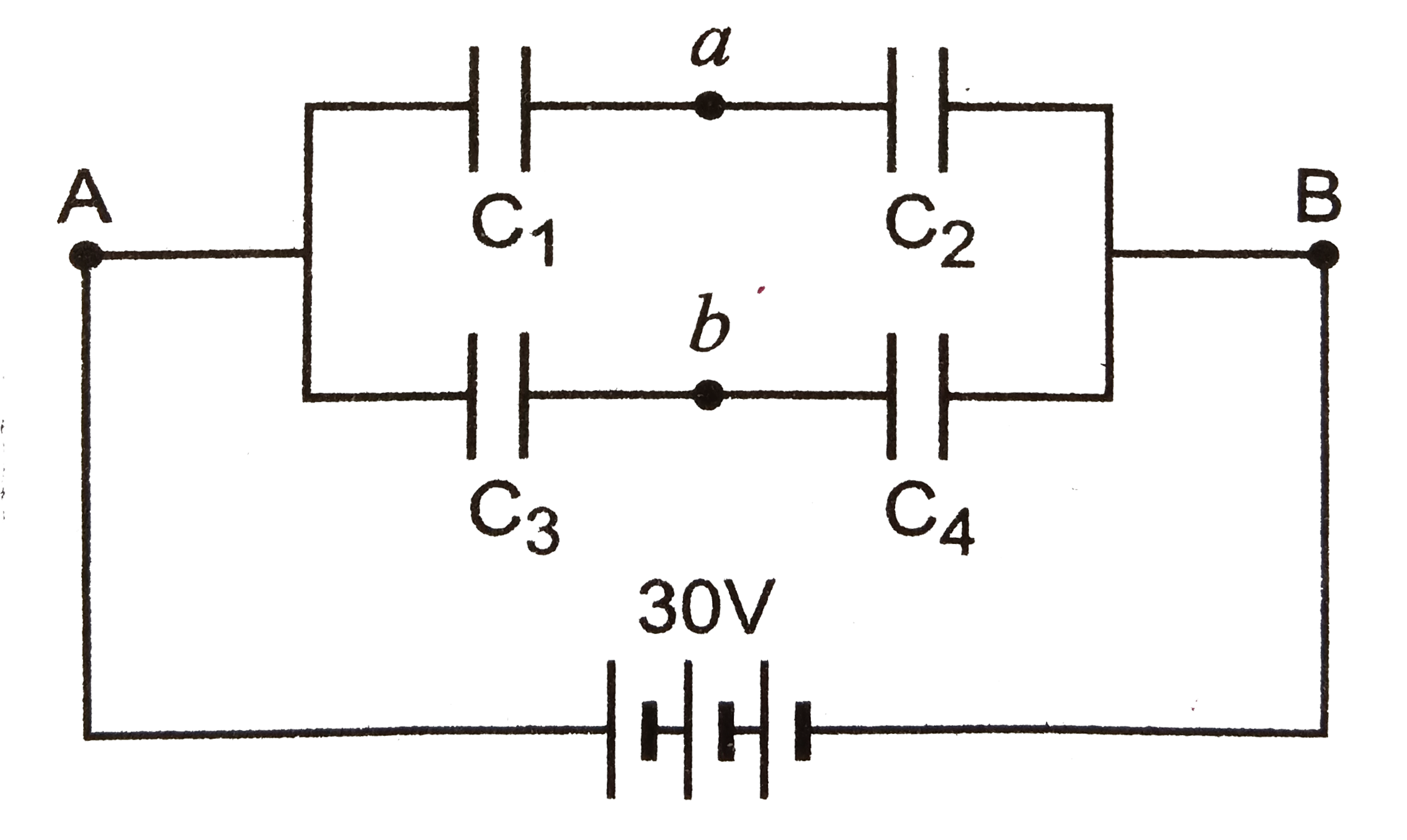
View SolutionFour capacitors with capacitances C1=1μF,C2=1.5μF,C3=2.5μF and C4=0.5μF are connected as shown in Fig, to a 30 voltg source. The potentail difference between points a and b is

View SolutionIn the given network capacitance, C1=10μF,C2=5μF and C3=4μF. What is the resultant capacitance between A and B?

View SolutionThe force between the plates of a parallel plate capacitor of capacitance C and distance of separation of the plates d with a potential difference V between the plates, is.
View SolutionThree capacitors of 2μF,3μFand6μF are joined in series and the combination is charged by means of a 24 V battery. The potential difference between the plates of the 6μF capacitor is
View Solution
