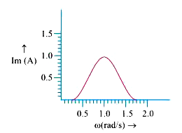
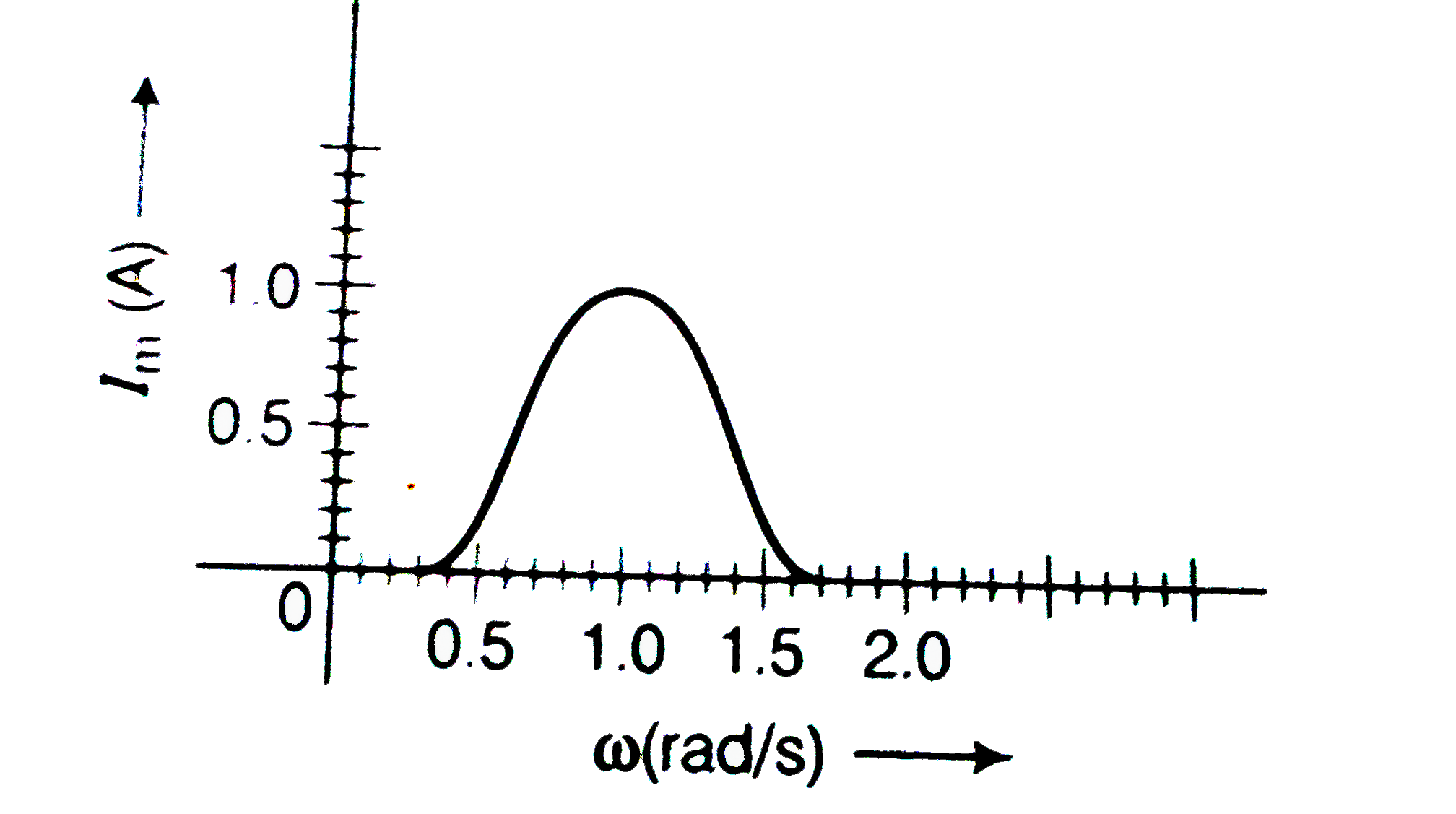
In series LCR circuit, the plot of Imax versus ω is shown in figure. Find the bandwidth and mark in the figure.
Video Solution
Text Solution
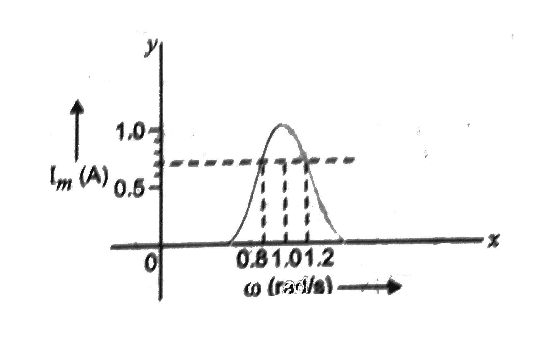
As is know for theory, bandwidth = frequency range at which
I=1√2Imax=0.7Imax.
In Fig. band width, Δω1.2−0.4rad/s.
|
Topper's Solved these Questions
- ELECTROMAGNETIC INDUCTION & ALTERNATING CURRENTBOOK - PRADEEPCHAPTER - ELECTROMAGNETIC INDUCTION & ALTERNATING CURRENTEXERCISE - Value Based Questions
2 Videos
- ELECTROMAGNETIC INDUCTION & ALTERNATING CURRENTBOOK - PRADEEPCHAPTER - ELECTROMAGNETIC INDUCTION & ALTERNATING CURRENTEXERCISE - Exercise
376 Videos
- ELECTROMAGNETIC INDUCTION & ALTERNATING CURRENTBOOK - PRADEEPCHAPTER - ELECTROMAGNETIC INDUCTION & ALTERNATING CURRENTEXERCISE - Long Answer Questions
9 Videos
- DUAL NATURE OF RADIATION AND MATTERBOOK - PRADEEPCHAPTER - DUAL NATURE OF RADIATION AND MATTEREXERCISE - Exercise
191 Videos
- ELECTROMAGNETIC WAVESBOOK - PRADEEPCHAPTER - ELECTROMAGNETIC WAVESEXERCISE - II Focus multiple choice question
5 Videos
Similar Questions
Knowledge Check
In LCR circuit as shown in figure
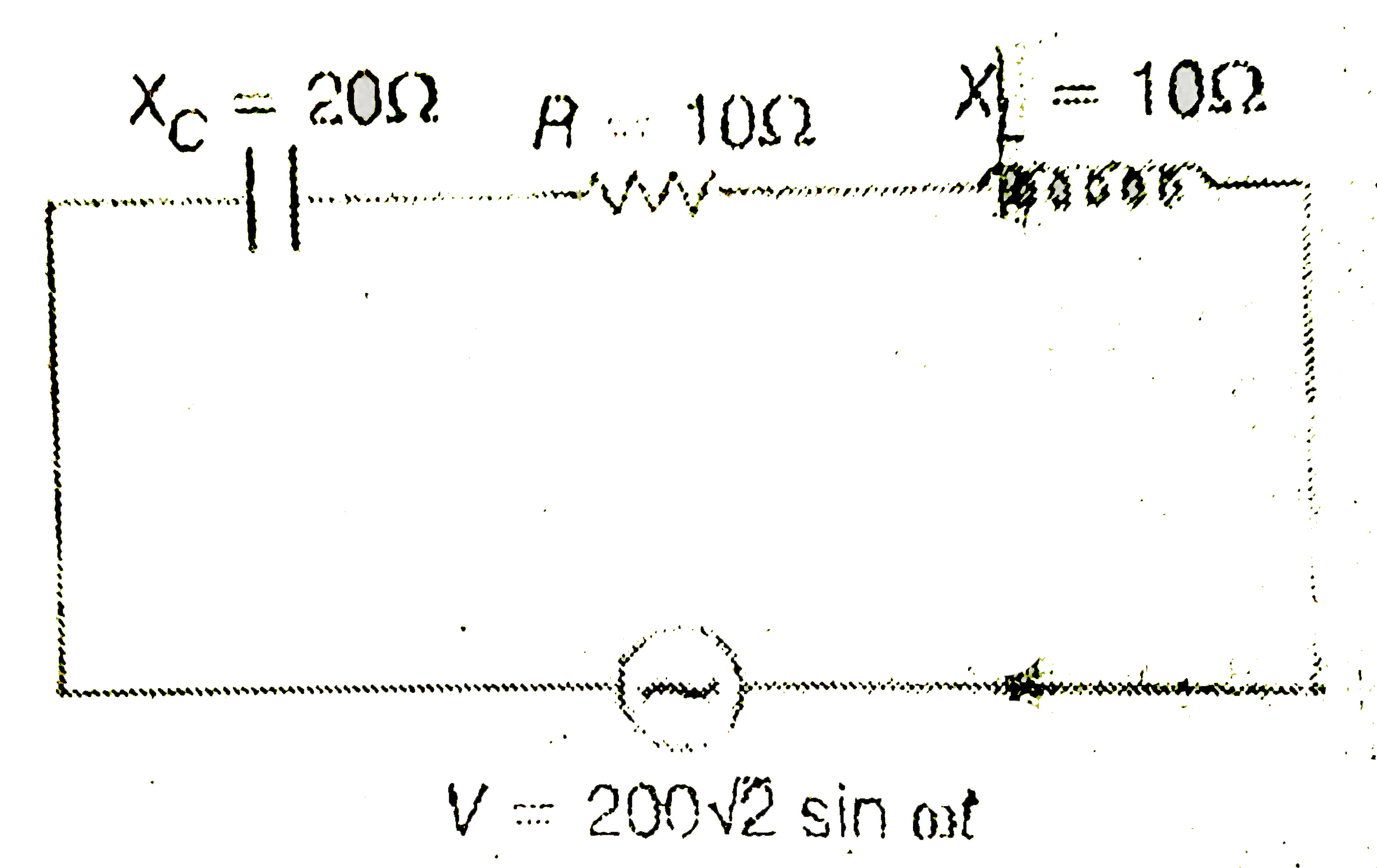 Acurrent will lead the voltageBrms value of current is 20ACpower factor of circuit is 1√2Dvoltage drop across resistance is 100V
In series LCR circuit, the voltages across R, L and C shown in figure. The voltage of applied source is
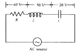 A110 voltB10 voltC50 voltD70 volt
In the series LCR circuit shown the impedance is
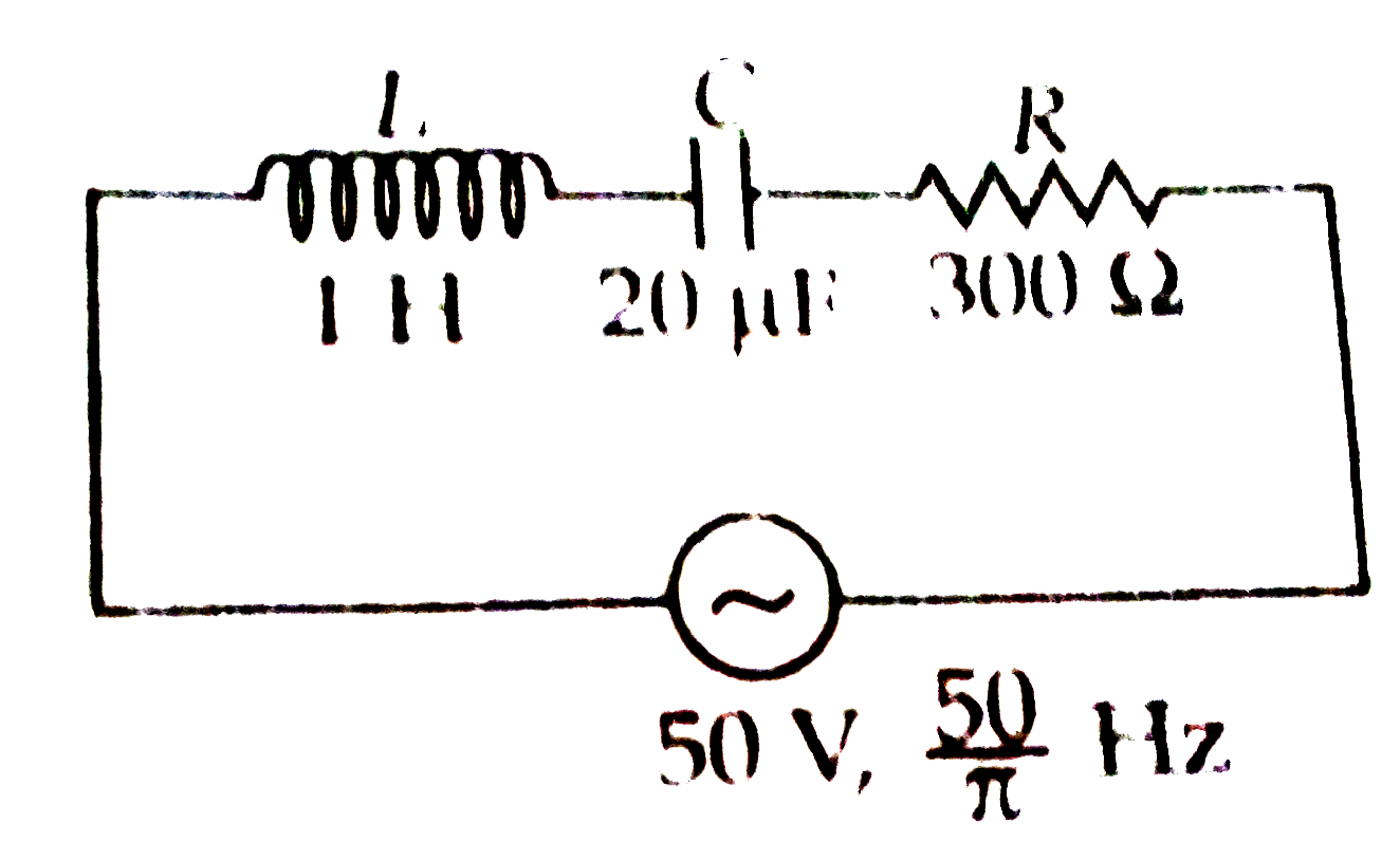 A200ΩB100ΩC300ΩD500Ω
In series LCR circuit, the plot of Imax versus ω is shown in figure. Find the bandwidth and mark in the figure.

View SolutionIn the series LCR circuit shown, the impedance is
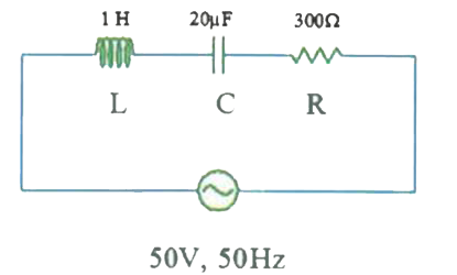
View SolutionIn the series LCR circuit shown, the impedance is

View SolutionIn series LCR circuit, the voltages across R, L and C are shown in the figure. The voltage of applied source
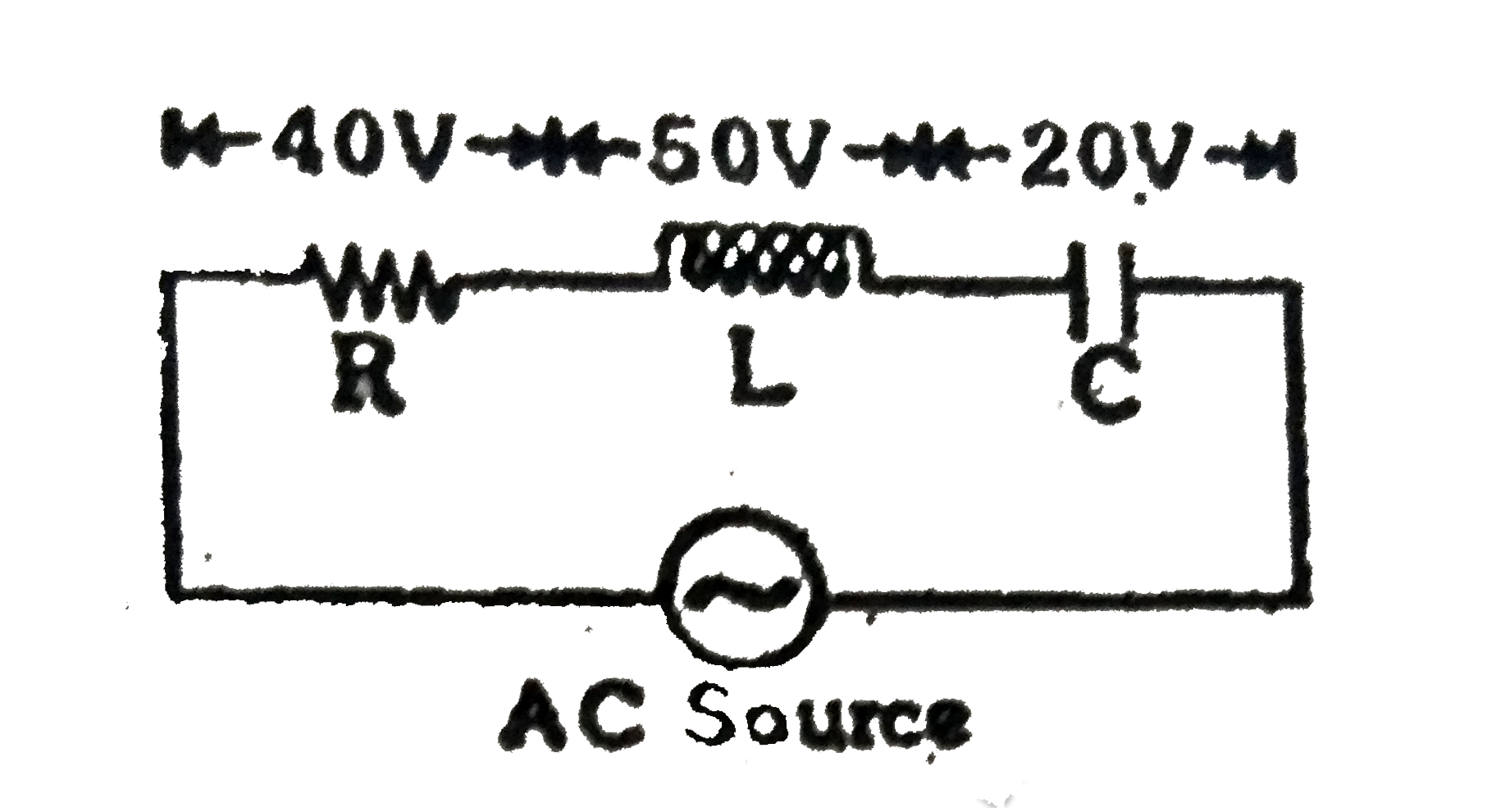
View SolutionIn the circuit shown in the figure, find the current in 45Ω

View Solution

