In the arrangement shown in figure, there are two coils wound on a non-conducting cylindrical rod. Initially the key is not inserted. Then the key is inserted and later removed. Then:
The deflection in the galvanometer remains zero throughout
There is a momentary deflection in the golvanometer but it dies out shortly and there is no effect when the key is removed.
There are momentary galvanometer deflections that die out shortly, the deflections are in the same diirection.
There are momentary galvanometer deflections that die out shortly, the deflections are in opposidte directions. Thus the galvanometer shows momentary deflections in opposite dierections.
The correct Answer is:D
To solve the problem step by step, we will analyze the behavior of the galvanometer when the key is inserted and then removed in the circuit with two coils.
Step 1: Understanding the Setup
In the given arrangement, we have two coils wound around a non-conducting cylindrical rod. Initially, the key (switch) is not inserted, meaning the circuit is open and no current flows through the coils.
Hint: Consider what happens to the current when the switch is closed and opened.
Step 2: Inserting the Key
When the key is inserted (closed), current starts to flow through the first coil. According to Faraday's law of electromagnetic induction, a changing magnetic field due to the current in the first coil will induce an electromotive force (emf) in the second coil.
Hint: Think about how the flow of current creates a magnetic field and how that affects the second coil.
Step 3: Observing the Galvanometer
As the current flows through the first coil, the galvanometer connected to the second coil will show a momentary deflection. This deflection occurs because of the induced emf in the second coil due to the changing magnetic field.
Hint: Remember that the galvanometer measures current, which is affected by changes in magnetic fields.
Step 4: Removing the Key
When the key is removed (opened), the current in the first coil suddenly decreases. This change in current creates a change in the magnetic field, which again induces an emf in the second coil. However, this time the induced current will flow in the opposite direction compared to when the key was inserted.
Hint: Consider how the direction of the current in the first coil affects the induced current in the second coil.
Step 5: Final Observations
1. When the key is inserted, the galvanometer shows a momentary deflection in one direction.
2. When the key is removed, the galvanometer shows a momentary deflection in the opposite direction.
Hint: Think about the relationship between the direction of current flow and the direction of the induced emf.
Conclusion
Based on the analysis:
- The galvanometer shows a momentary deflection when the key is inserted and a momentary deflection in the opposite direction when the key is removed.
- Therefore, the correct option would be that there are momentary galvanometer deflections that die out shortly, and the deflections are in opposite directions when the key is inserted and removed.
In the given arrangement, we have two coils wound around a non-conducting cylindrical rod. Initially, the key (switch) is not inserted, meaning the circuit is open and no current flows through the coils.
When the key is inserted (closed), current starts to flow through the first coil. According to Faraday's law of electromagnetic induction, a changing magnetic field due to the current in the first coil will induce an electromotive force (emf) in the second coil.
As the current flows through the first coil, the galvanometer connected to the second coil will show a momentary deflection. This deflection occurs because of the induced emf in the second coil due to the changing magnetic field.
When the key is removed (opened), the current in the first coil suddenly decreases. This change in current creates a change in the magnetic field, which again induces an emf in the second coil. However, this time the induced current will flow in the opposite direction compared to when the key was inserted.
1. When the key is inserted, the galvanometer shows a momentary deflection in one direction.
2. When the key is removed, the galvanometer shows a momentary deflection in the opposite direction.
Based on the analysis:
- The galvanometer shows a momentary deflection when the key is inserted and a momentary deflection in the opposite direction when the key is removed.
- Therefore, the correct option would be that there are momentary galvanometer deflections that die out shortly, and the deflections are in opposite directions when the key is inserted and removed.
Topper's Solved these Questions
- MAGNETIC EFFECTS OF ELECTRIC CURRENT BOOK - NCERT EXEMPLAR ENGLISHCHAPTER - MAGNETIC EFFECTS OF ELECTRIC CURRENT EXERCISE - SHORT ANSWER TYPE QUESTIONS
12 Videos
- MAGNETIC EFFECTS OF ELECTRIC CURRENT BOOK - NCERT EXEMPLAR ENGLISHCHAPTER - MAGNETIC EFFECTS OF ELECTRIC CURRENT EXERCISE - LONG ANSWER TYPE QUESTIONS
8 Videos
- LIGHT : REFLECTION AND REFRACTIONBOOK - NCERT EXEMPLAR ENGLISHCHAPTER - LIGHT : REFLECTION AND REFRACTIONEXERCISE - Long Answer Type Questions
9 Videos
- MANAGEMENT OF NATURAL RESOURCESBOOK - NCERT EXEMPLAR ENGLISHCHAPTER - MANAGEMENT OF NATURAL RESOURCESEXERCISE - Long Answer Type Questions
6 Videos
Similar Questions
Two rods of equal cross sections area are joined end the end as shown in figure. These are supported between two rigid vertical walls. Initially the rods are unstrained .
_E01_228_Q01.png)
If temperature of system is increased by ΔT then thermal stress developed in first rod-
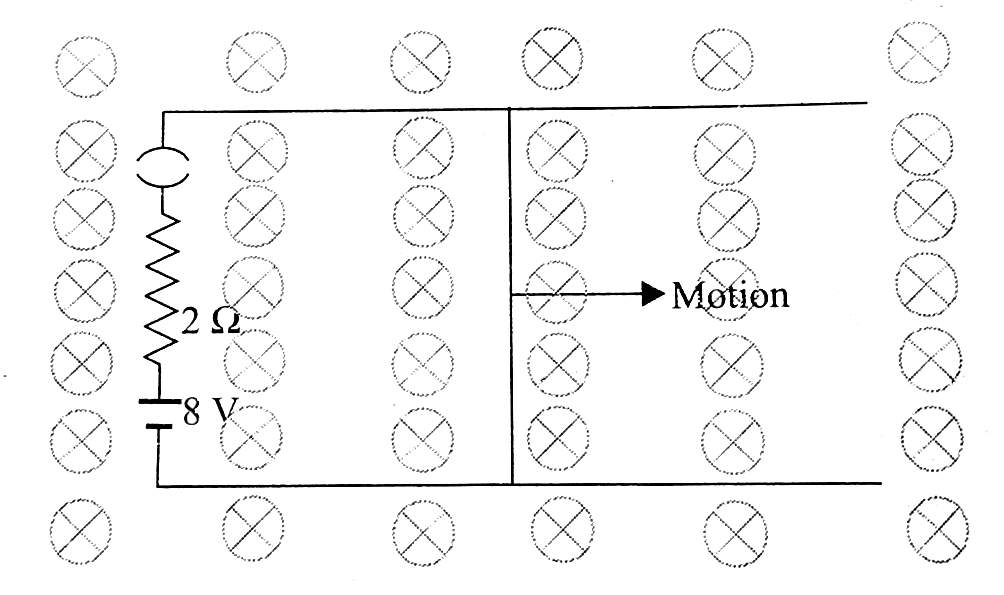
View SolutionFigure shows a conducting frame having battery and a resistance on which a movable conductor of length 0.5 m can slide, The whole arrangement is placed in a uniform magnetic field of B =0.4 T directed perpendicular and into the plane of frame. Initially the circuit is open. When the key is inserted, the conductor begins to move. It is found that a force 0.5 N has to be applied on the conductor to the left to keep it moving at constant speed to the right.
Current flowing in the conductor is:
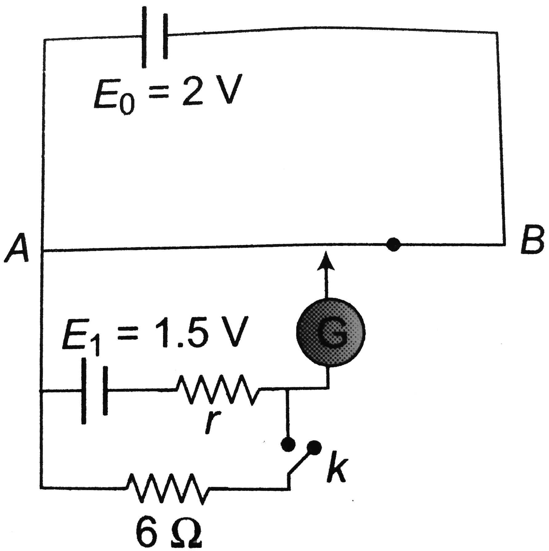
View SolutionFor the arrangement of the potentimeter shown in the figure, The balance point is obtained at a distance 75cm from A when the key k is open
The second balance point is obtained at 60cm from A when the key k is closed. Find the internal resistance of the battery E1.
View SolutionTwo rods of equal cross sections area are joined end the end as shown in figure. These are supported between two rigid vertical walls. Initially the rods are unstrained .
_E01_227_Q01.png)
If temperature of system is increased by ΔT then junction will not shift if -
View SolutionTwo rods of equal cross sections area are joined end the end as shown in figure. These are supported between two rigid vertical walls. Initially the rods are unstrained .
_E01_229_Q01.png)
If temperature of system is increased by ΔT then shifting in junction if junction if Y1α1>Y2α2 is given by -
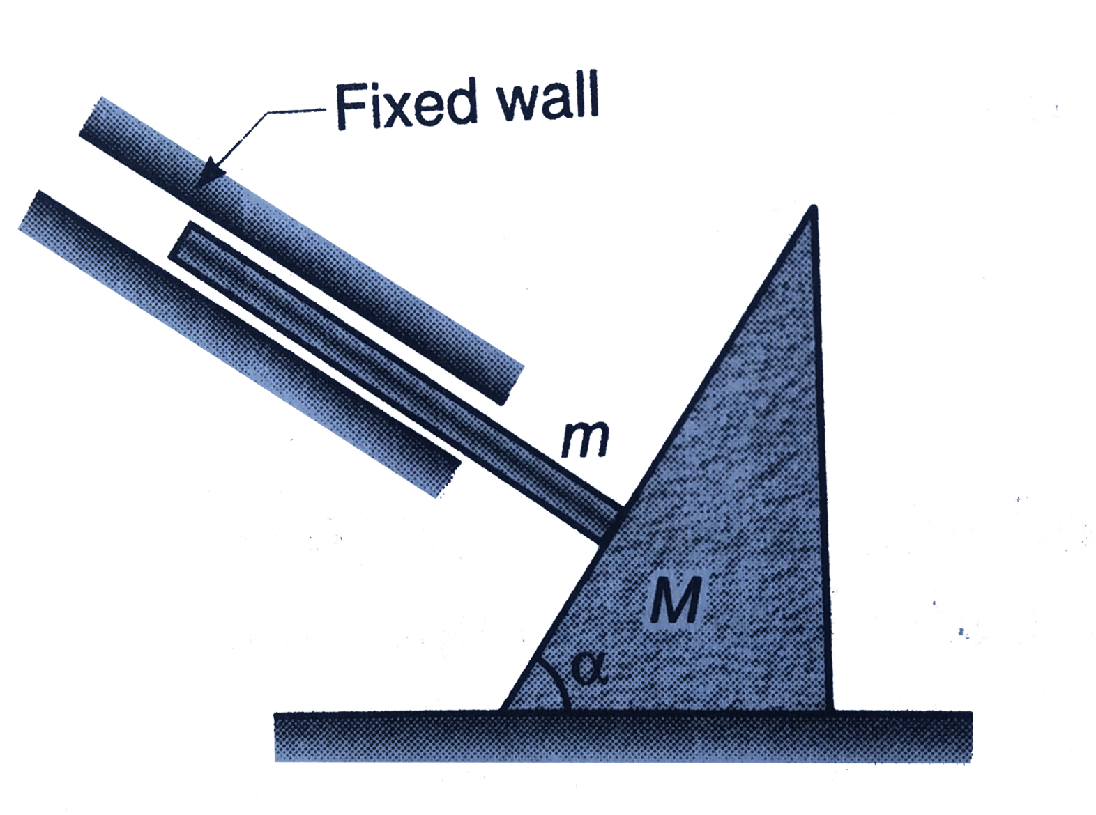
View SolutionIn the arrangement shown in figure, the rod of mass mheld by two smooth walls, remains always perpendicular to the surface of the wedge of mass M. Assumming all the surface to be frictionless, find the acceleration of the rod and that of the wedge.

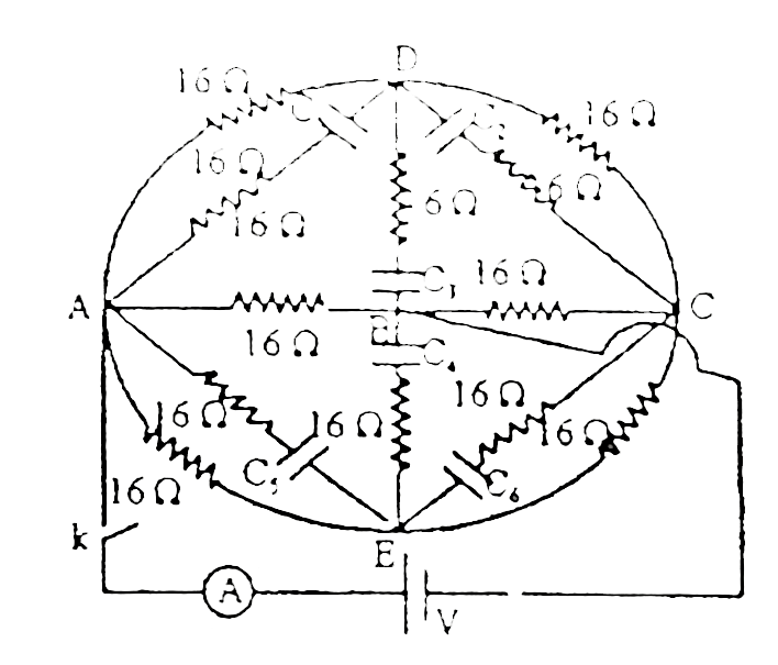
View SolutionThe resistance each of 16Ω and capacitance of each 100μF are arranged as shown in the figure. A battery of emf 12V is joined across A and B. Find the
(i) reading of the ammeter just after key is ciosed and after long time.
(ii) charges in each capacitors when steady state is achieved.
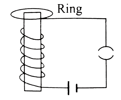
View SolutionFigure shows a powerful electromagnet arrangement. A copper ring, which is free to move, is placed on the projecting part of the core as shown.
When the key is inserted, the ring
View SolutionIn the arrangement shown in the figure , the rod of mass m held by two smooth walls , remain always perpendicular to the surface of the wedge of mass M . Assuming all the surface are frictionless, find the acceleration of the rod wedge.
View SolutionConsider the arrangement shown in figure. Friction coefficient for all the surfaces are shown in the figure and the rod connecting two upper blocks is horizontal.

What is the minimum value F so that the rear two blocks start sliding with each other :
View Solution
