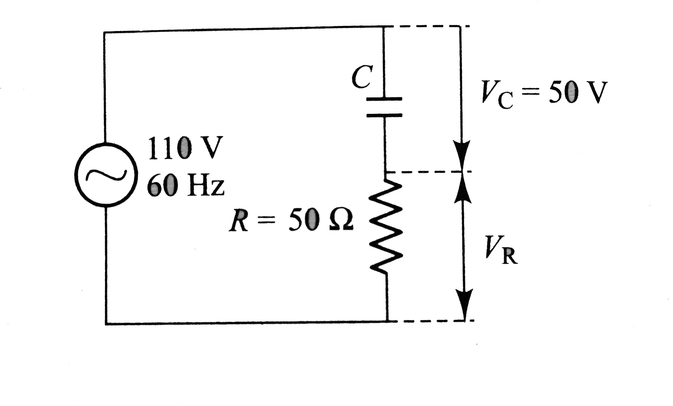
In the circuit given in fig. (VC)=50VandR=50Ω. The values of C and (VR) are
(A) 3.3mF, 60V
(B) 104μF, 98V
(C) 52μF, 98V
(D) 2μF, 60V
The correct Answer is:B
V2C+V2R=V2
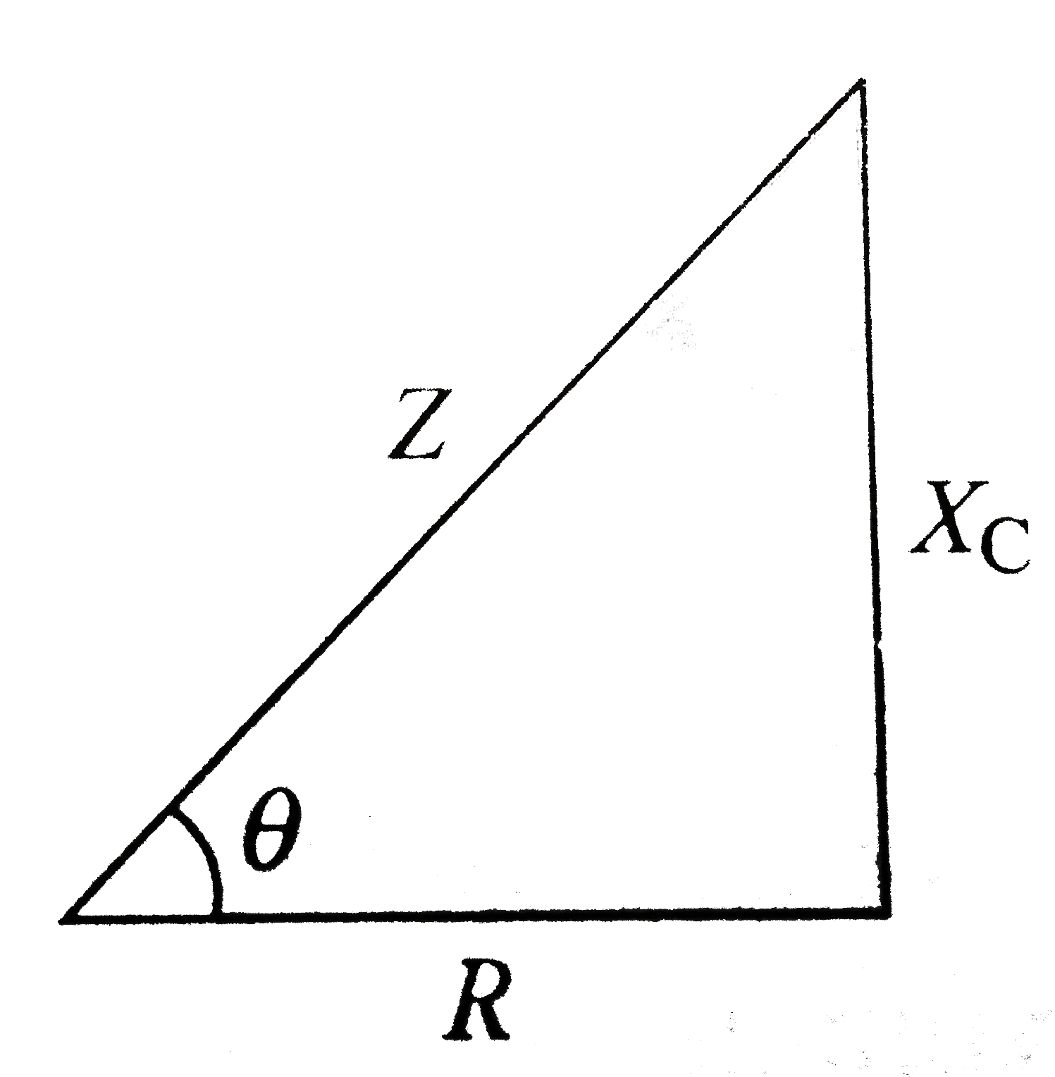
502+V2R=1102⇒VR=√160×60=98V
then, (IV)=√160×6050R=50Ω
alos (IV)=110√R2+X2C∴9850=110502+X2C
Flux, (XC) and now using (XC)=1ωC, we get C=104(μ)F.
Topper's Solved these Questions
- ALTERNATING CURRENTBOOK - CENGAGE PHYSICSCHAPTER - ALTERNATING CURRENTEXERCISE - Exercises Multiple Correct
5 Videos
- ALTERNATING CURRENTBOOK - CENGAGE PHYSICSCHAPTER - ALTERNATING CURRENTEXERCISE - Exercises Assertion-reasoning
7 Videos
- ALTERNATING CURRENTBOOK - CENGAGE PHYSICSCHAPTER - ALTERNATING CURRENTEXERCISE - Exercises Subjective
15 Videos
- OSCILLATIONSBOOK - CENGAGE PHYSICSCHAPTER - OSCILLATIONSEXERCISE - QUESTION BANK
39 Videos
- ATOMIC PHYSICSBOOK - CENGAGE PHYSICSCHAPTER - ATOMIC PHYSICSEXERCISE - ddp.4.3
15 Videos
Similar Questions
A series LCR circuit is connected top an AC power source of 220 V , 50 Hz. The values of L and R are 0.41 H and 80Ω respectively. What is the value of C if current and voltage are in phase ?
View SolutionIn the circuit shown in fig. R1=10Ω,R2=Ω,C1=1μF,C2=2μF, and E =6V. Calculate the charge on each capactor in the stedy state.
View Solution
Knowledge Check
200 V ac source is fed to series LCR circuit having XL=50Ω,XC=50Ω and R=25Ω. Potential drop across the inductor is
A100 VB200 VC400 VD10 V
In the circuit shown in figure
R1=30Ω,R2=40Ω,L=0.4H and C=13mF.
Find seven function of time I,I1,I2,VR1,VL,VR2 and VC. Also total power consumed in the circuit. In the given potential function V is in volts and omega in rad/s.
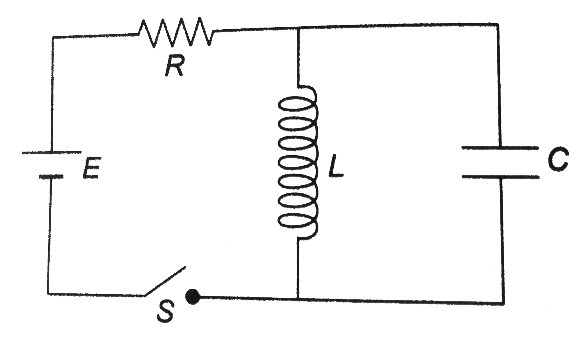
View SolutionIn the circuit shown in the figure, E=50.0V,R=250Ω and C=0.500μF. The switch S is closed for a long time, and no voltage is measured across the capacitor. After the switch is opened, the voltage across the capacitor reaches a maximum value of 150V. What is the inductance L?
View SolutionFind a potentail difference φ1−φ2 between points 1 and 2 of the circuit shown in Fig if R11=10Ω,R2=20Ω,E1=5.0V, and E2=2.0V. The internal resisances of the current sources are negligible.

View SolutionDetermine the voltage drop across the resistor R1 in the circuit given below with E = 65V, R_1 = 50 OmegaR_2 = 100 Omega, R_3 = 100 Omega, and R_4 300 Omega.
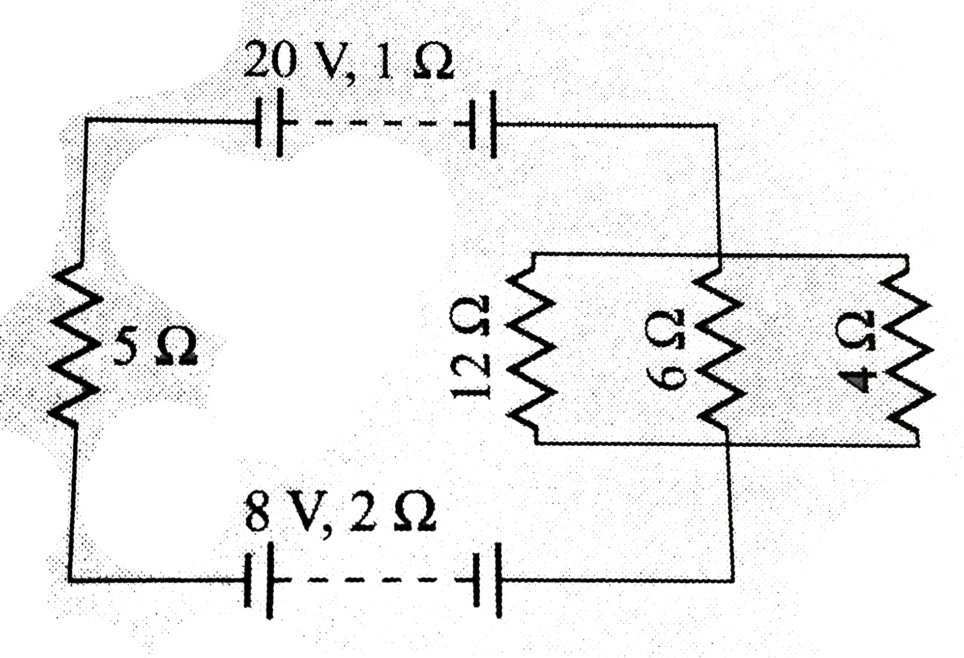
View SolutionIn the circuit shown in Fig. 4.19. R1=100Ω,R2=R3=50Ω,R4=75Ω and E=4.75 V. Work out the equivalent resistance of the circuit and the current in each resistor.
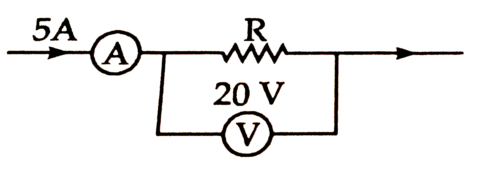
View SolutionIn the adjacent circuit the ammeter reads 5.0 A and voltmeter reads 20V. The value of resistance R is
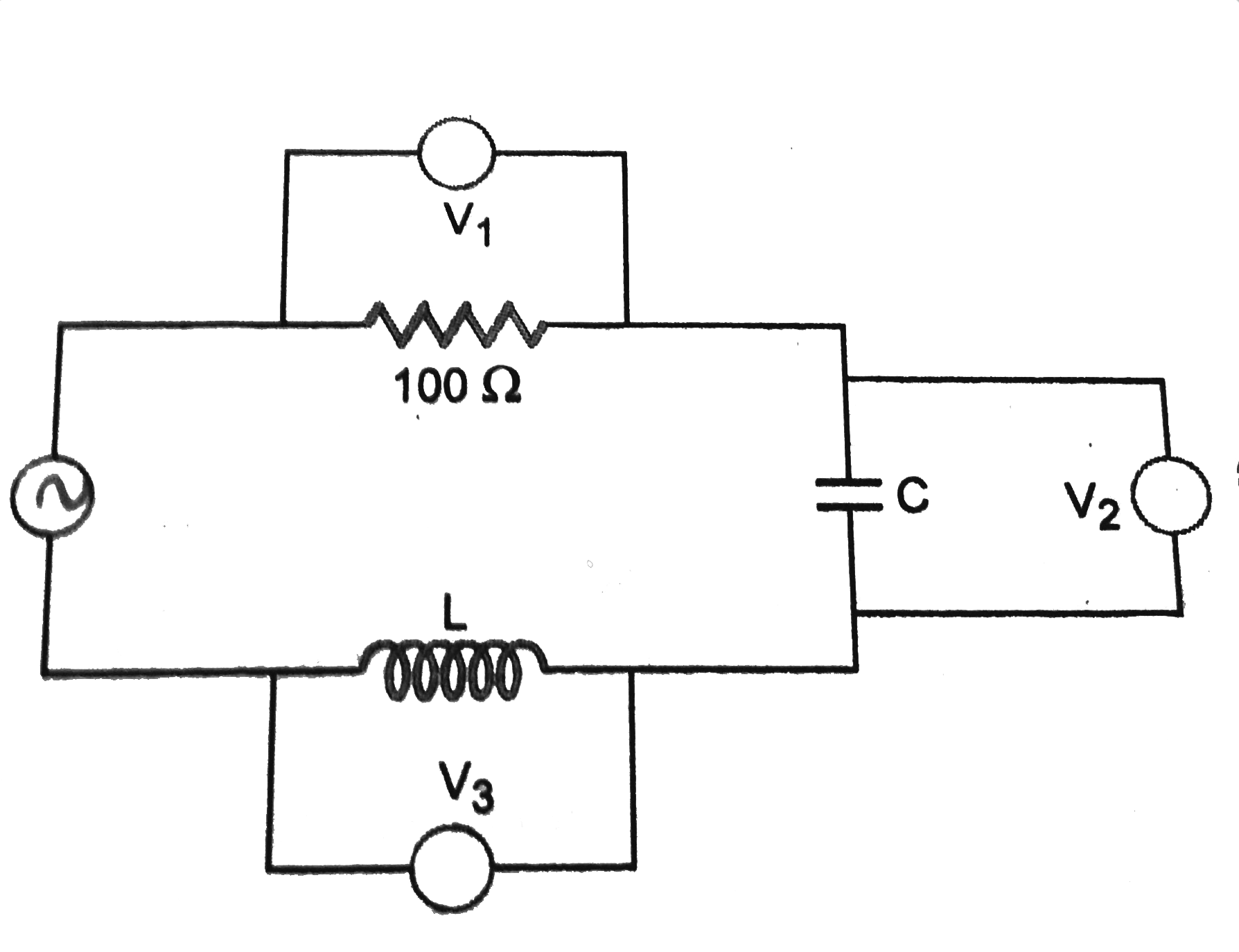
View SolutionA series LCR circuit is connected to an a.c. source 220 V - 50 Hz as shown in fig. If the reading of the three voltemeters V1,V2,V3 are 65 V, 415 V and 204 V respectively. Calculate (i) current in the circuit (ii) value of inductor L (ii) value of capacitor C (iv) value of C for same L required to produce resonance.
View Solution
