In the circuit shown, A and B are equal resistances. When S is closed, the capcitor Ccharges from the cell of emf epsilon and reaches a steady state.
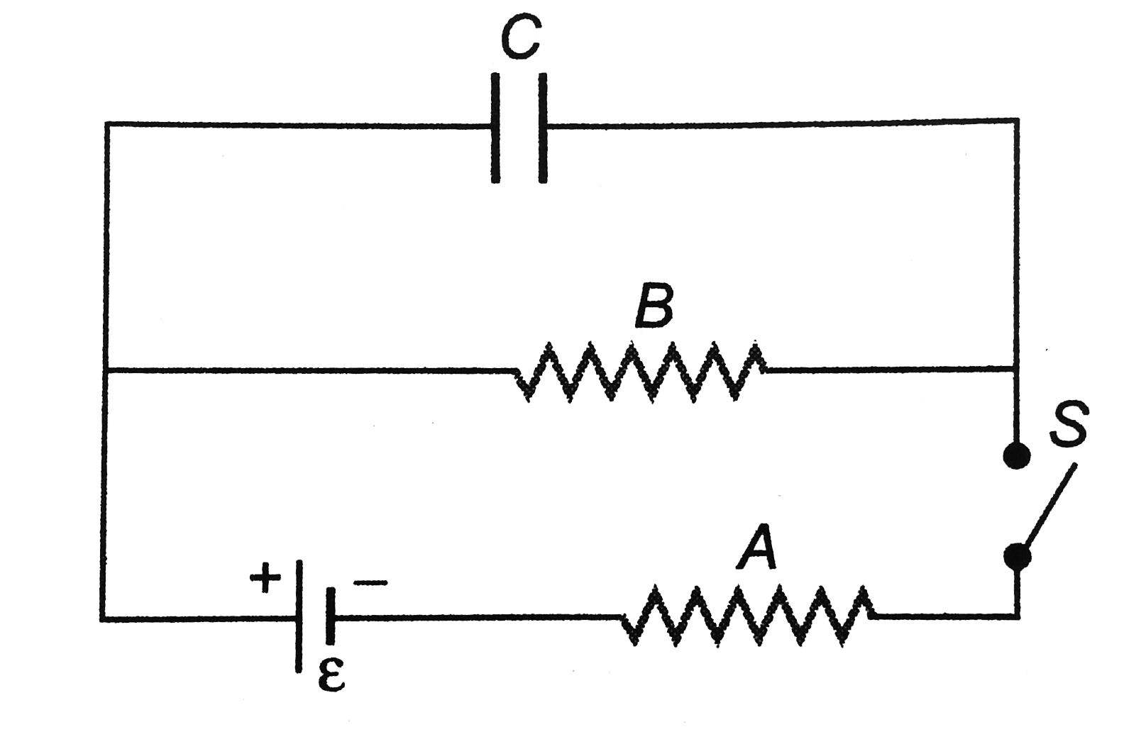
During charging more heat is produced in A and B
In the steady state,heat is produced at te same rate in A and B
In the steady state, energy stored in C is 14Cɛ2
In the steady state, energy stored in C is 18Cɛ2
The correct Answer is:A, B, D
Step by step video, text & image solution for In the circuit shown, A and B are equal resistances. When S is closed, the capcitor Ccharges from the cell of emf epsilon and reaches a steady state. by Physics experts to help you in doubts & scoring excellent marks in Class 12 exams.
Updated on:21/07/2023Topper's Solved these Questions
Similar Questions
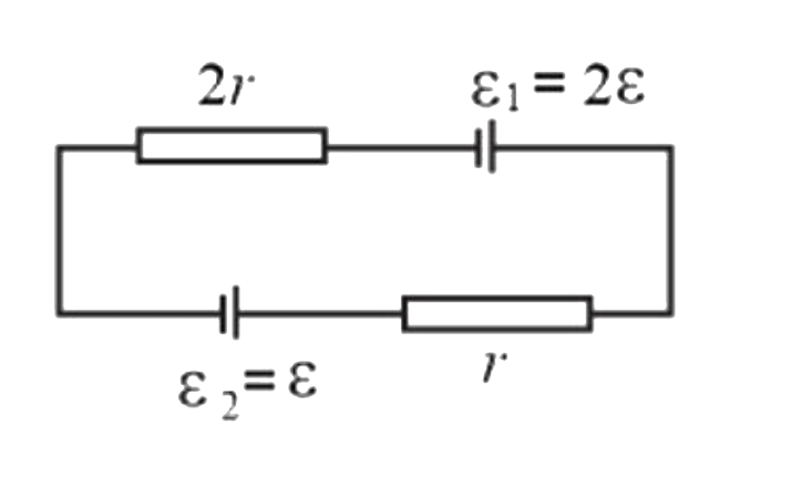
In the circuit shown if the internal resistance of each cell is r, then the rate at which the chemical energy of ε1 is being consumed is
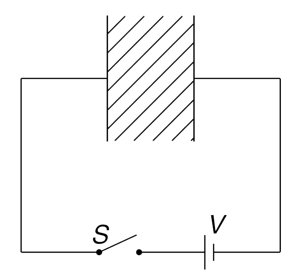
View SolutionA parallel plate capacitor has plate area A and separation between the plates equal to d. A material of dielectric constant K and resistivity ρ is filled between the plates. The switch is closed to connect the capac- itor to a cell of emf V.
(a) Write the steady state current in the circuit and charge on the capacitor.
(b) When the circuit is in steady state, switch s is opened (at t = 0). Write charge on the capacitor as function of time (t) after this
View Solution
Knowledge Check
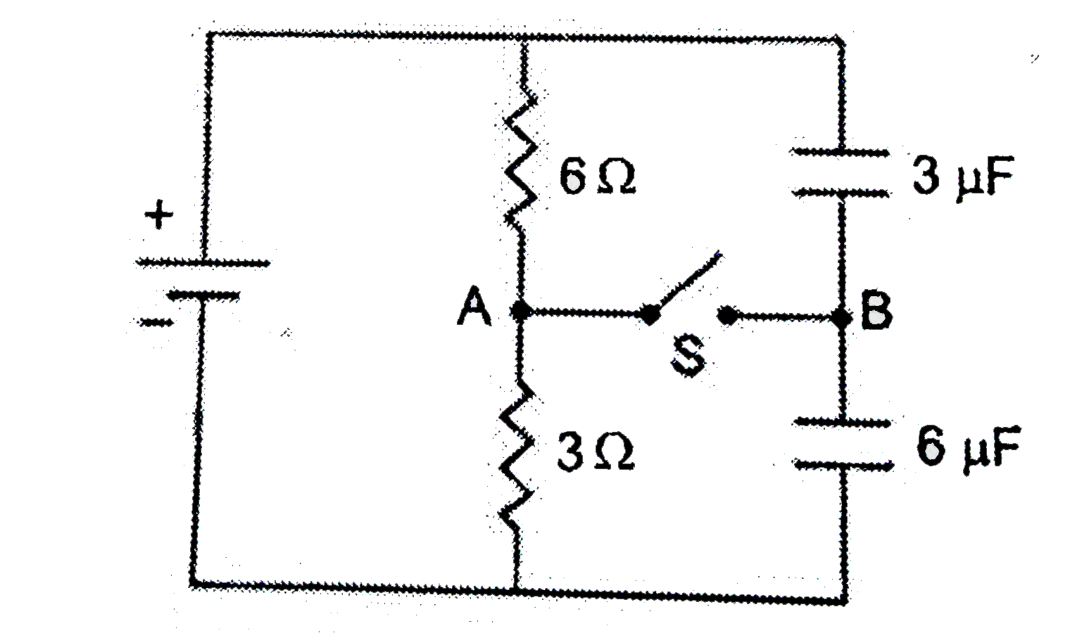
In the circuit shown above, when then switch S is closed,Ano charge flows through SBcharge flows from A to BCcharge flows from B to ADcharge flows initially from A to B and later from B to AIn the circuit shown, the resistances are given in ohms and the battery is assumed ideal with emf equal to 3.0 V.
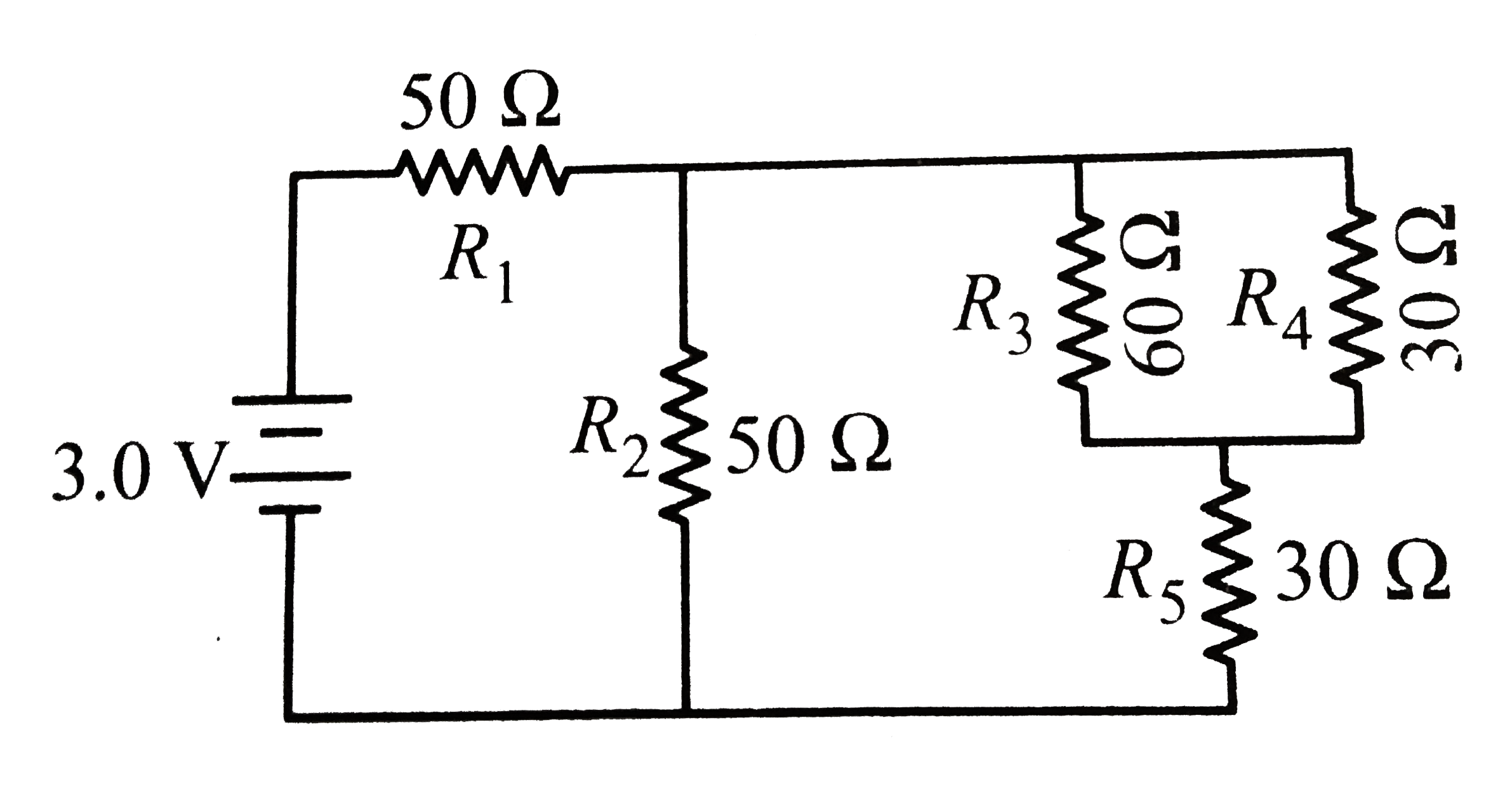 AThe resistor R5 that dissipates maximum power.BThe resistor R1 that dissipates maximum power.CThe potential difference across resistor R3is0.4V.DThe current passing through 3 V battery is 40 mA.
In the circuit shown, what is the energy stored in the coil at steady state is closed to?
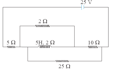 A21.3JB42.6JCZeroD213J
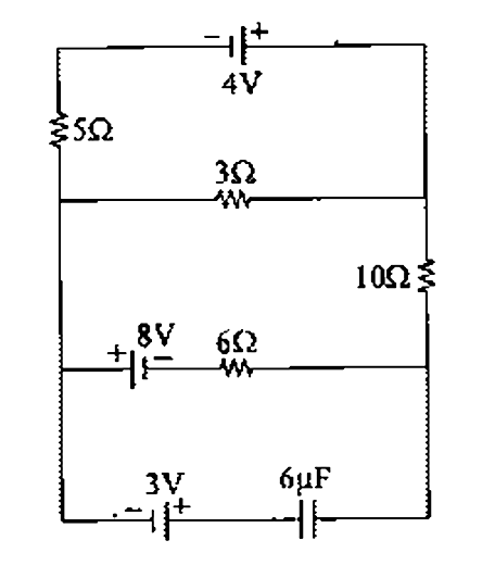
In the circuit shown in figure-3.166 the cells are ideal Calculate(a) The current in 3Ω resistance (b) Current the cell the 8V cell and (c) The steady state charge on the capacitor.
View SolutionIn the circuit shown in the figure, in steady state:

The current drawn from the battery is
View SolutionIn the circuit shown in figure switch S is closed at time t=0
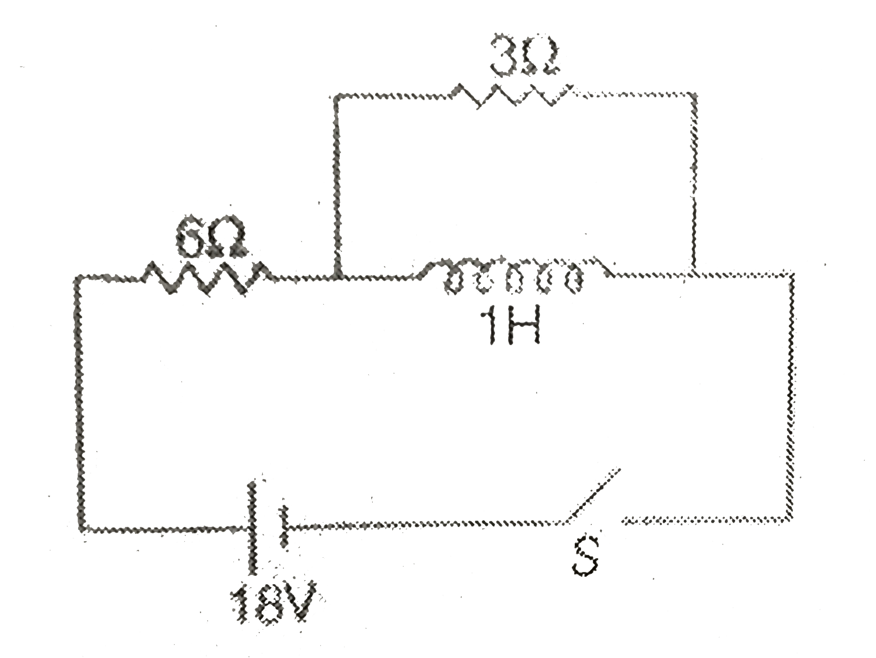
At what time current through 3Ω resistance and 1H inductor are equal?
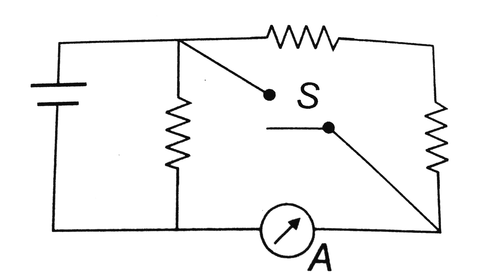
View SolutionIn the circuit shown, the reading of the Ammter is doulbed after the switch is closed. Each resistor has a resistance =1Ω and the ideal cell has an e.m.f. =10V. Then the ammeter has a resistance equal to
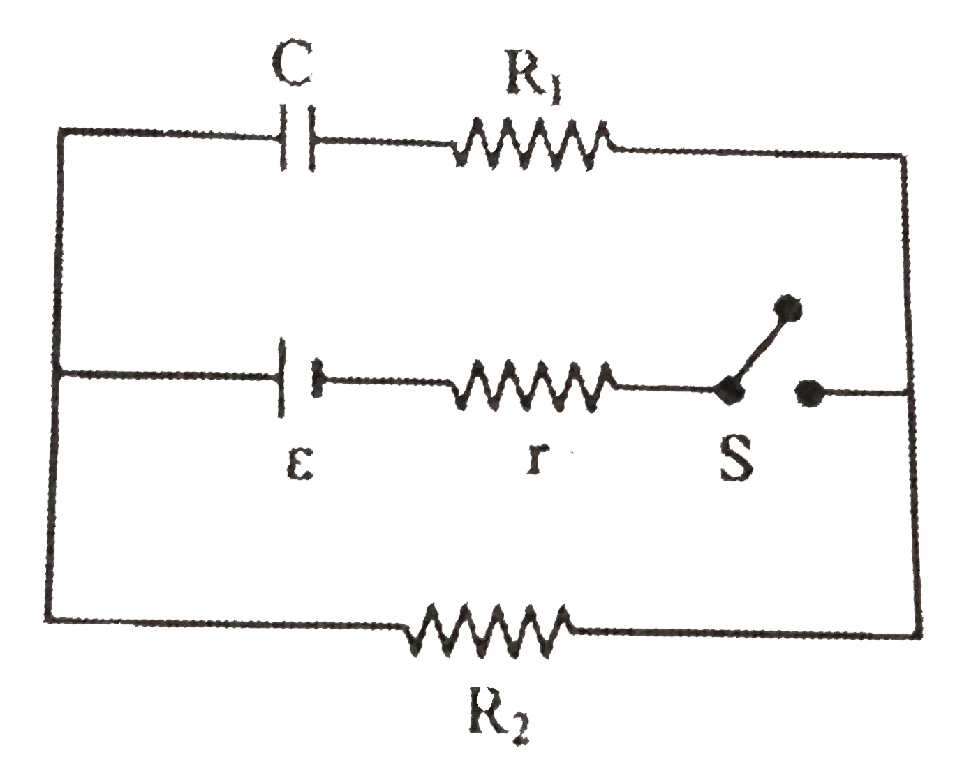
View SolutionIn given circuit, switch S is closed at t=0 . The charge on the capacitor ar steady state will be
View Solution
