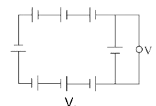
In the circuit shown below, V should be:
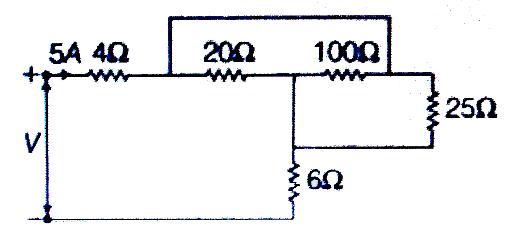
50V
100V
75V
25V
The correct Answer is:B
Step by step video, text & image solution for In the circuit shown below, V should be: by Physics experts to help you in doubts & scoring excellent marks in Class 11 exams.
Updated on:21/07/2023Topper's Solved these Questions
Similar Questions
Knowledge Check
The circuit shown below acts as
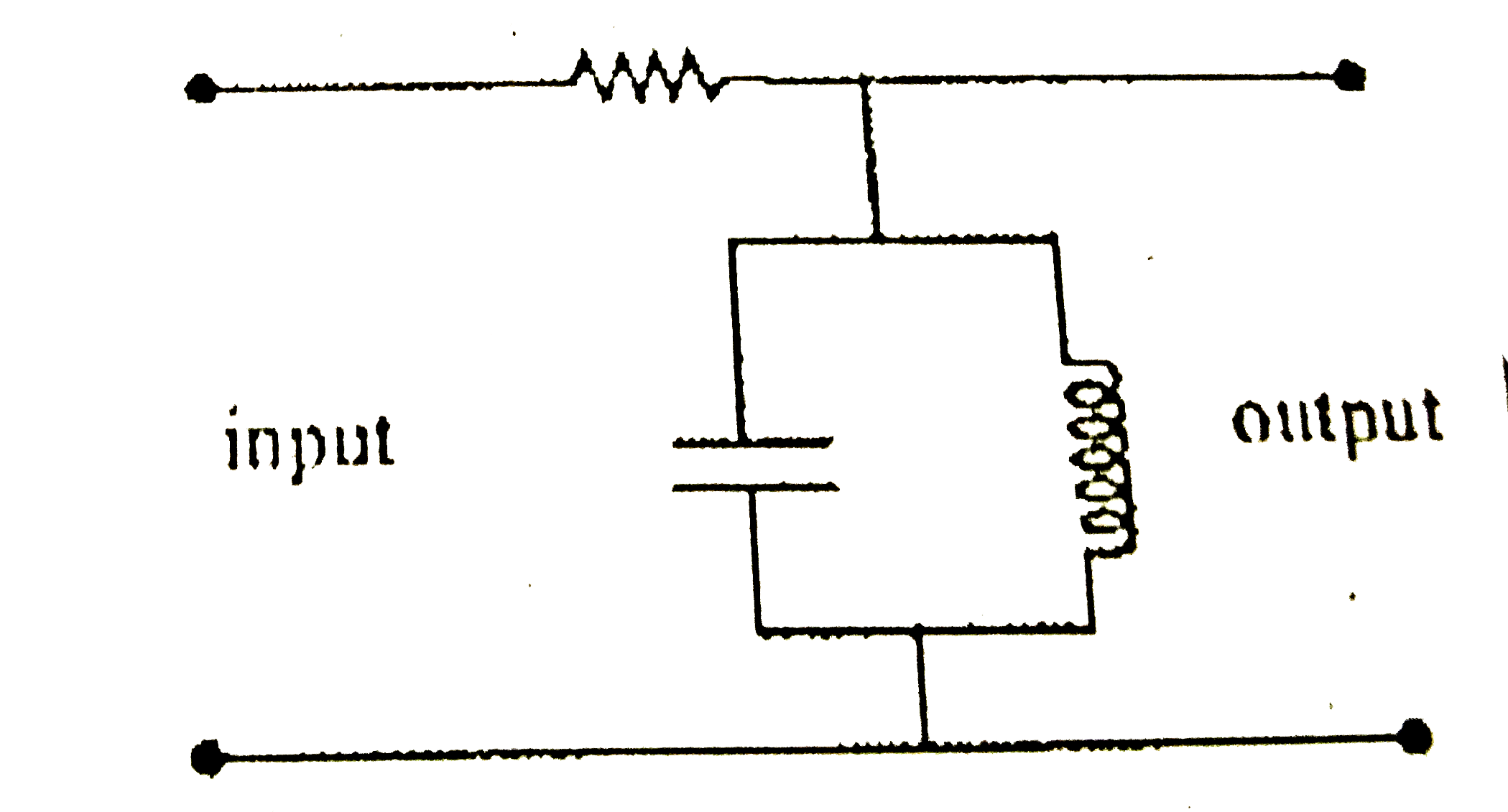 Atuned filterBlow pass filterChigh pass filterDrectifier
The circuit shown below acts as
 Ahigh pass filterBlow pass filterCtuned filterDrectifier
In the circuit shown below, what will be the reading of the voltmeter and ammeter?
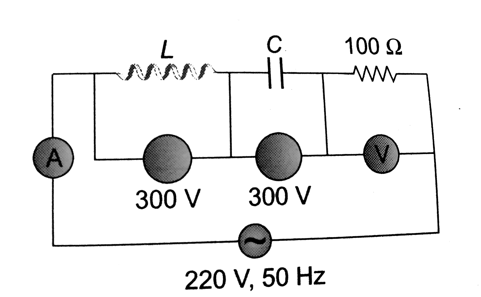 A800V,2AB300V,2AC220V,2.2AD100V,2A
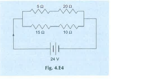
In the circuit shown below, calculate the total resistance of the circuit and the current flowing through it.
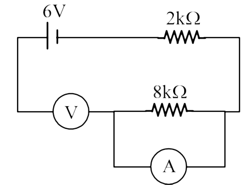
View SolutionIn the circuit shown below, a student performing Ohm’s law experiment accidently puts the voltmeter and the ammeter as shown in the circuit below, the reading in the voltmeter will be close to
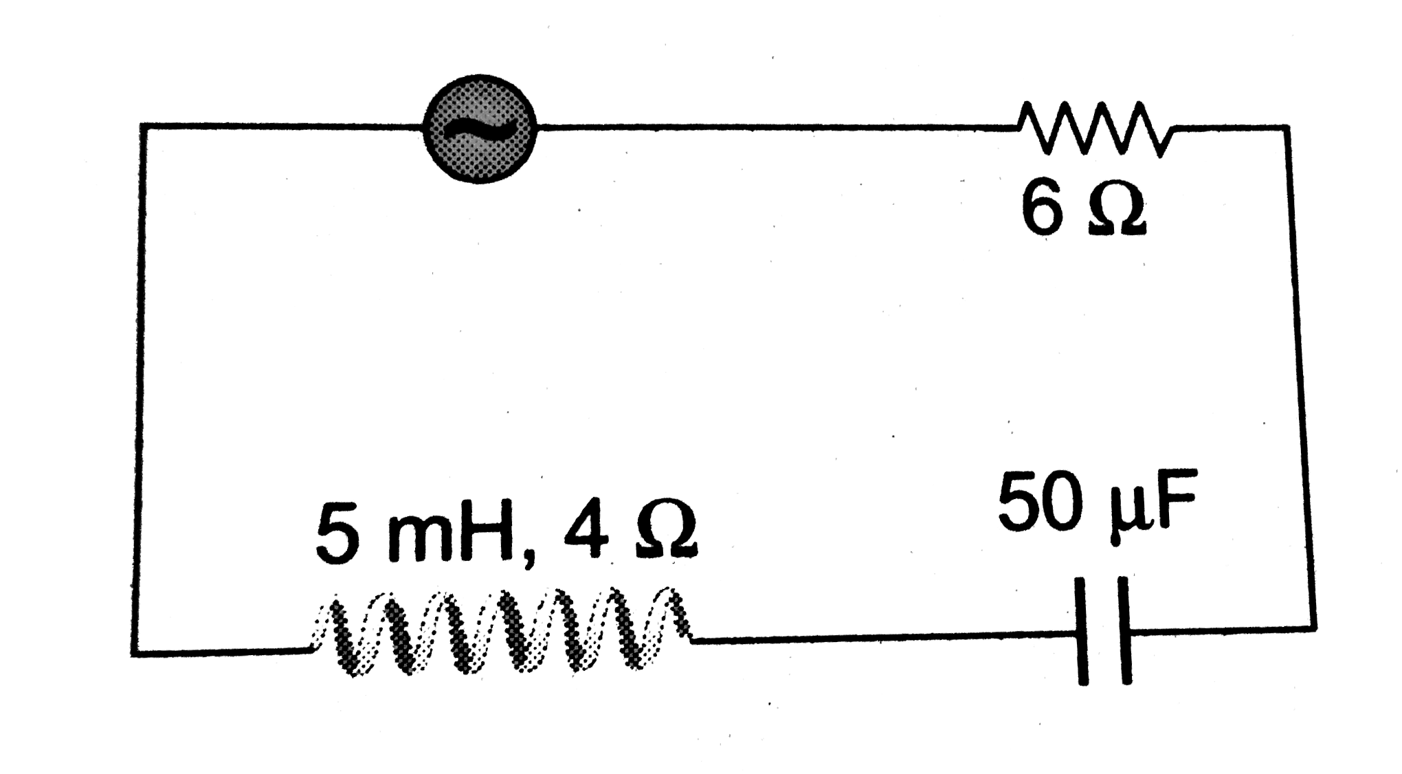
View SolutionIn the circuit below, the AC source the voltage V=20cos(ωt) volts with ω=2000rad/sec. The amplitude of the current will be nearest to
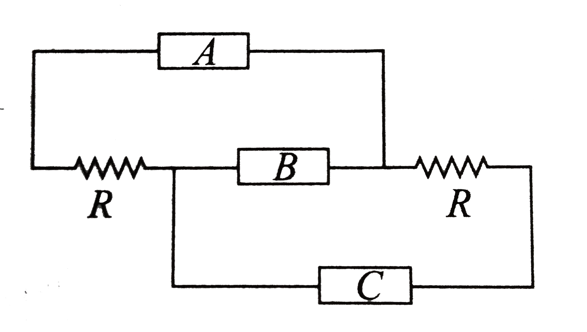
View SolutionA circuit is shown below.
View SolutionIn the circuit shown below, the ammeter A reads 5 A and the voltmeter V reads 20 V The correct value of resistance R is

View Solution

