In the circuit shown, each capacitor has a capacitance C. The emf of the cell is E. If the switch S is closed
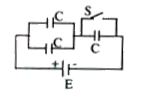
positive charge will flow out of the positive terminal of the cell
positive charge will enter the positive terminal of the cell
the amount of charge flowing through the cell will be CE.
the amount of charge flowing through the cell will be 4/3 CE.
The correct Answer is:A, D
Step by step video & image solution for In the circuit shown, each capacitor has a capacitance C. The emf of the cell is E. If the switch S is closed by Physics experts to help you in doubts & scoring excellent marks in Class 12 exams.
Updated on:21/07/2023Topper's Solved these Questions
- CAPACITORS BOOK - AAKASH SERIESCHAPTER - CAPACITORS EXERCISE - LECTURE SHEET (EXERCISE - III) (LEVEL - II (ADVANCED)) (Linked Comprehension Type Questions Passage )
5 Videos
- CAPACITORS BOOK - AAKASH SERIESCHAPTER - CAPACITORS EXERCISE - LECTURE SHEET (EXERCISE - III) (LEVEL - II (ADVANCED)) (Integer Type Questions )
3 Videos
- CAPACITORS BOOK - AAKASH SERIESCHAPTER - CAPACITORS EXERCISE - LECTURE SHEET (EXERCISE - III) (LEVEL - I (MAIN)) (Straight Objective Type Questions )
3 Videos
- ATOMSBOOK - AAKASH SERIESCHAPTER - ATOMSEXERCISE - PRACTICE EXERCISE
21 Videos
- COMMUNICATION SYSTEM BOOK - AAKASH SERIESCHAPTER - COMMUNICATION SYSTEM EXERCISE - LECTURE SHEET (LEVEL - I) (MAIN) (EXERCISE - IV) (Straight Objective & More than one Correct Answer Type Questions)
20 Videos
Similar Questions
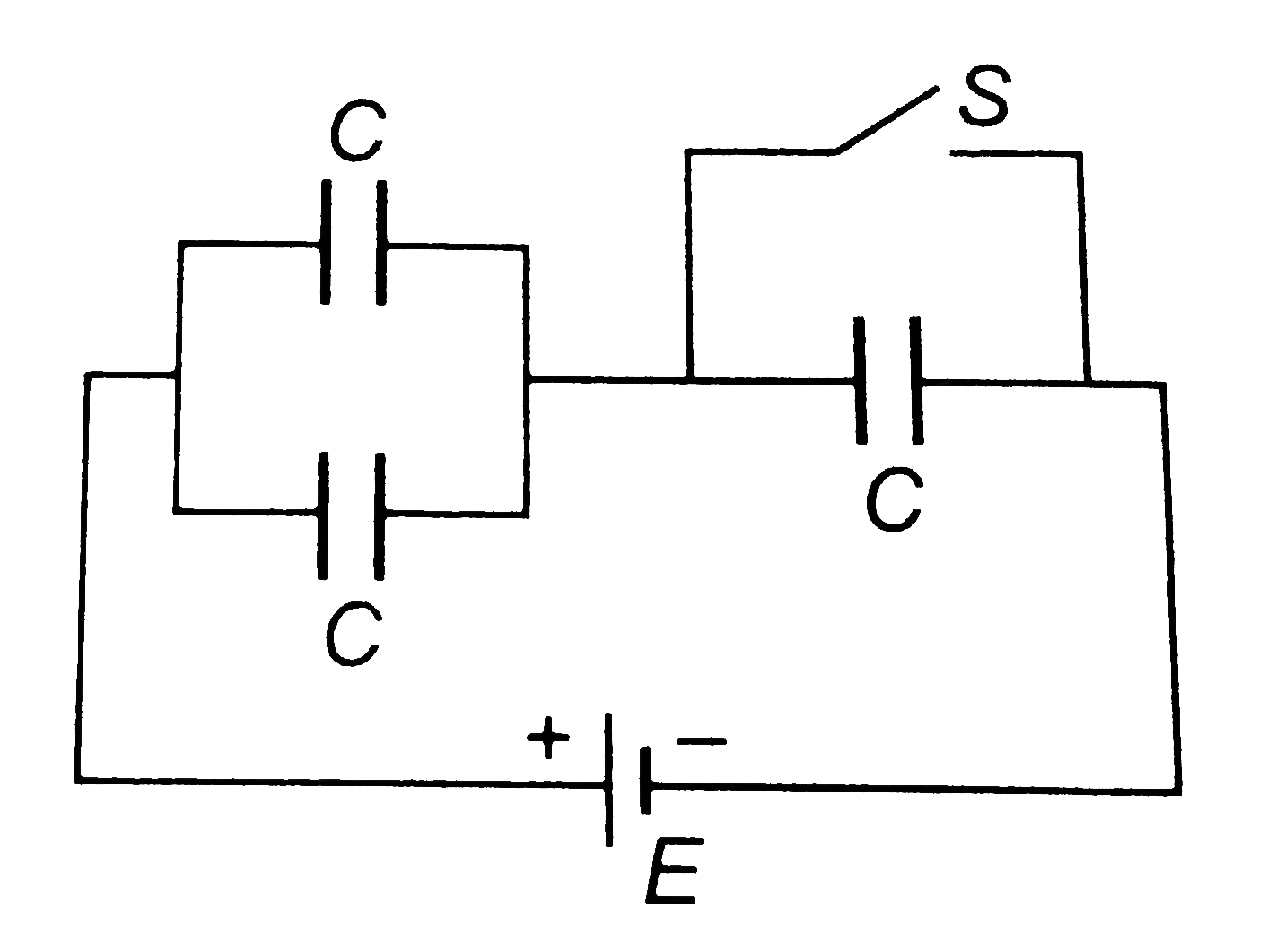
In the circuit shown each capacitor has a capcitance C. The emf of the celll is E. If the switch S is closed then
View SolutionIn the circuit shown each capacitor has a capcitance C. The emf of the celll is E. If the switch S is closed then

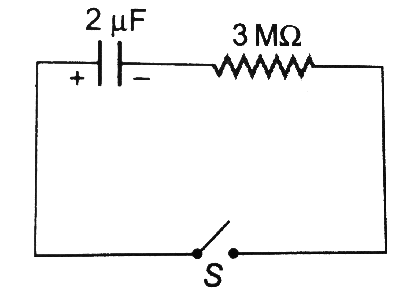
View SolutionIn the circuit shown in figure, the capacitor is charged with a cell of 5V.If the switch is closed at t=0, then at t=12s, charge on the capacitor is
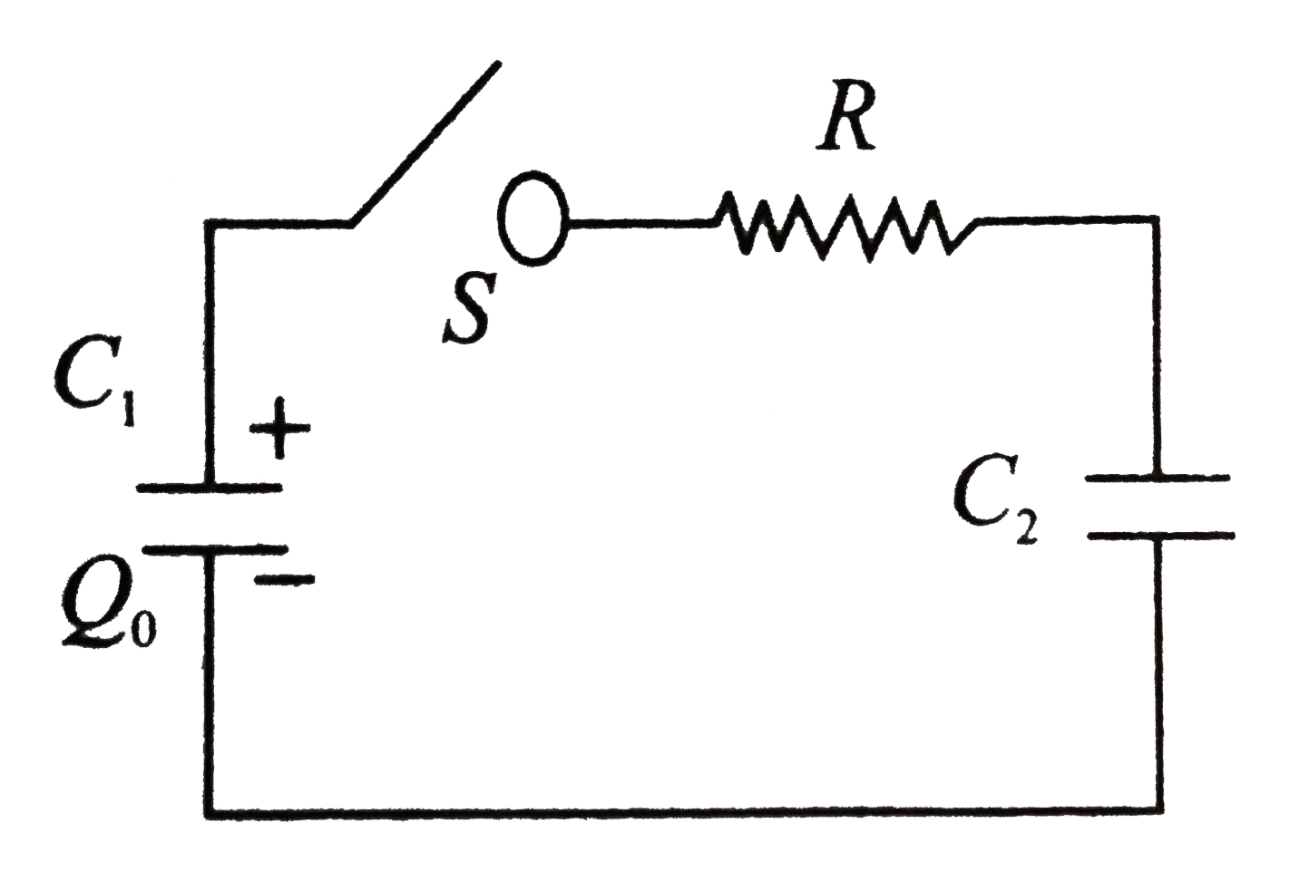
View SolutionIn the circuit shown, the capacitor C1 is initially charged with charge q0. The switch S is closed at time t = 0 . The charge on C2 after time t is
View SolutionIn the pure inductive circuit, the curves between frequency f and reciprocal of inductive reactance 1/XL is
View SolutionFind the capacitance between P and O. Each capacitor has capacitance C.
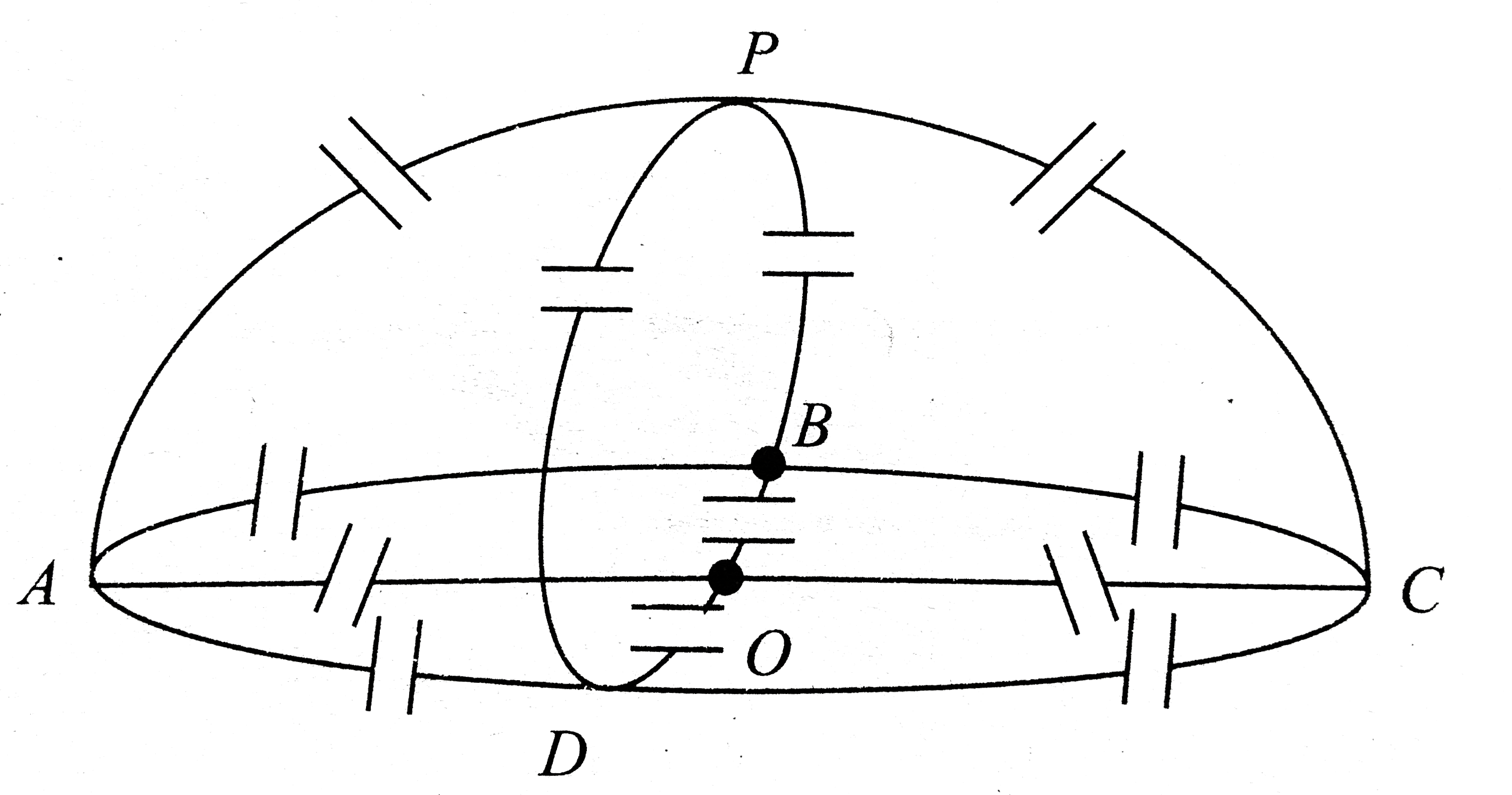 .
.
View Solution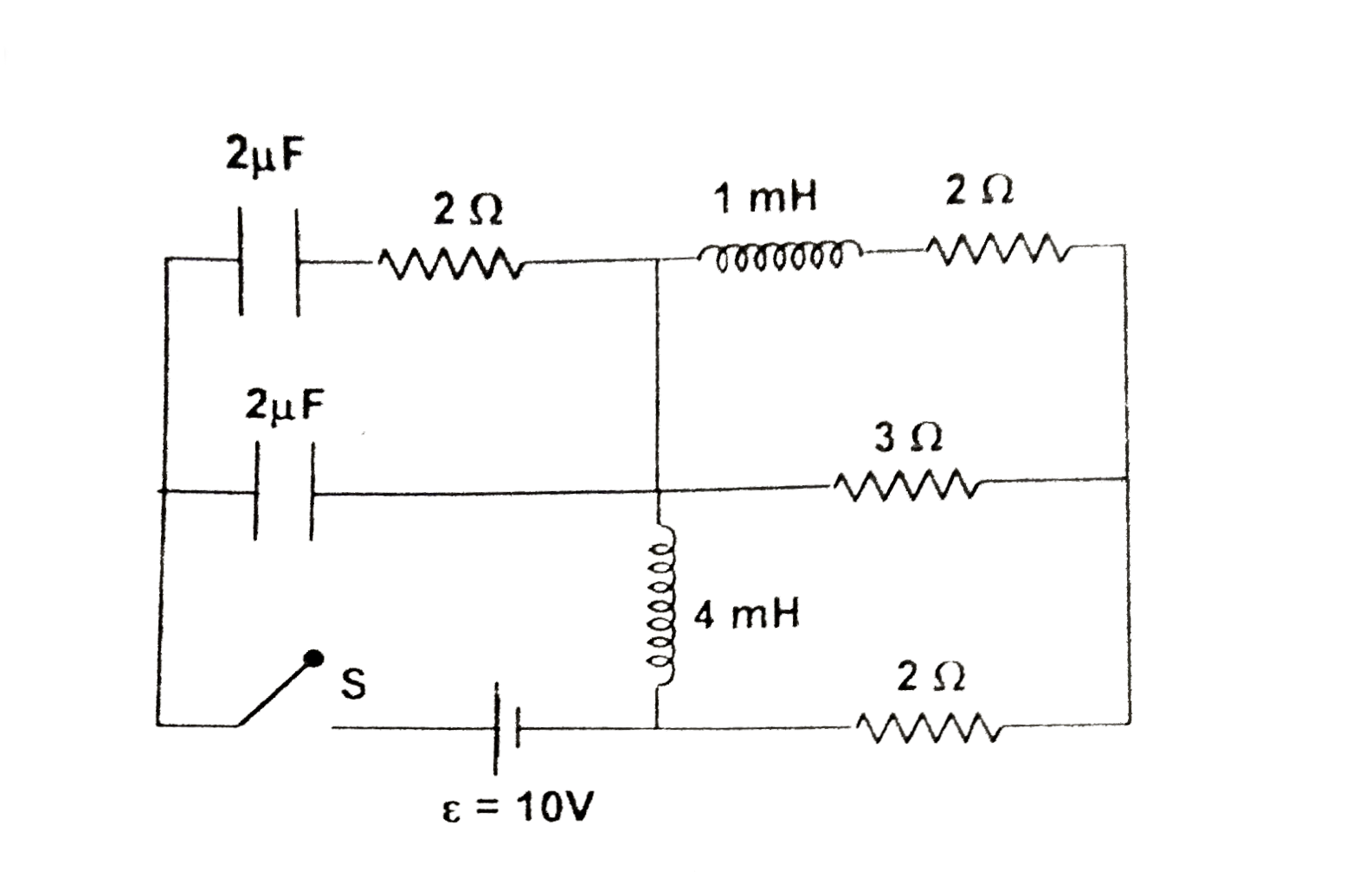
In the circuit shown, all the capacitors are initially uncharged. The current through the battery just after closing the switch 'S' is
View SolutionPassage-III
In the circuit shown, the battery is ideal with emf V. The capacitor is initially uncharged. The switch is closed at time t = 0
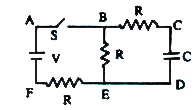
The current in the branch BE at t=∞ is
View SolutionA capacitor of capacitance C1 is charged to a potential difference V and then connected with an uncharged capacitor of capacitance C2 a resistance R. The switch is closed at t = 0. Choose the correct option(s):
View SolutionPassage-III
In the circuit shown, the battery is ideal with emf V. The capacitor is initially uncharged. The switch is closed at time t = 0
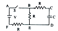
The current in branch containing capacitors at any time t is
View Solution
