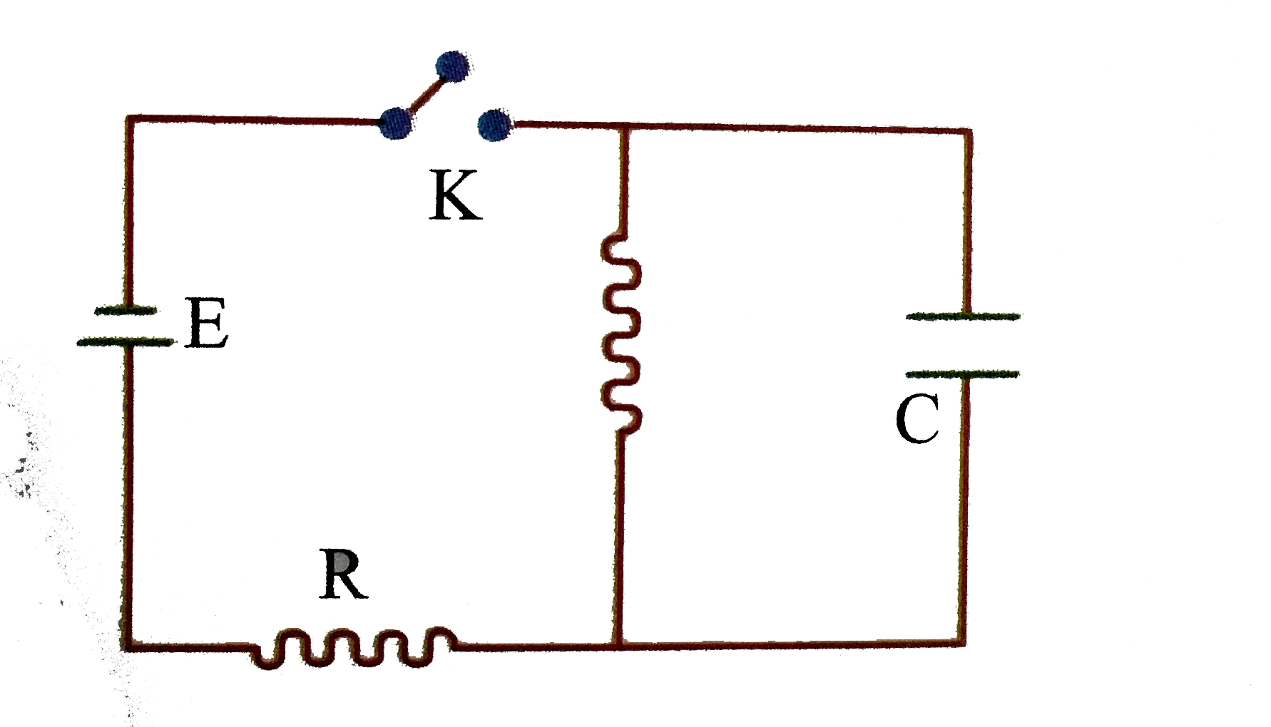
In the circuit shown each capacitor has a capcitance . The emf of the celll is . If the switch is closed then
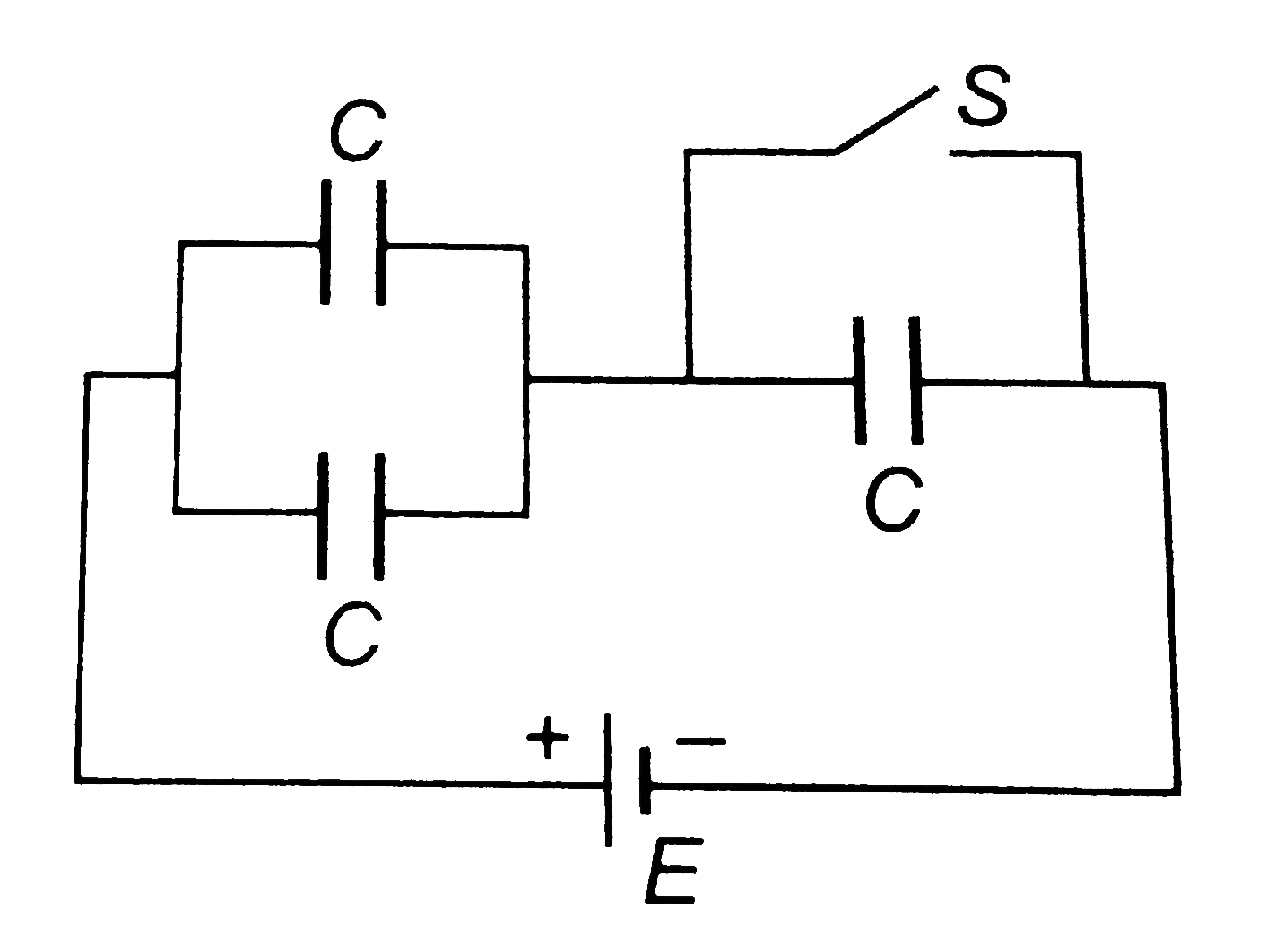
Positive charge wil flow out of the positive terminal of the cell
Positive charge will enter the positive terminal of the cell
the amount of the charge flowing through the cell will be CE
the amount of charge flowing through the cell is
The correct Answer is:A, D
Topper's Solved these Questions
- CAPACITORSBOOK - DC PANDEYCHAPTER - CAPACITORSEXERCISE - OBJECTIVE_TYPE
1 Videos
- CAPACITORSBOOK - DC PANDEYCHAPTER - CAPACITORSEXERCISE - OBJECTIVE_TYPE
1 Videos
- ATOMSBOOK - DC PANDEYCHAPTER - ATOMSEXERCISE - MEDICAL ENTRANCES GALLERY
42 Videos
- COMMUNICATION SYSTEMBOOK - DC PANDEYCHAPTER - COMMUNICATION SYSTEMEXERCISE - Subjective
11 Videos
Similar Questions
In the circuit shown in figure, each capacitor has a capacitance C and cell voltage is E. If switch S is closed, then calculate the work done by battery after closing the switch.

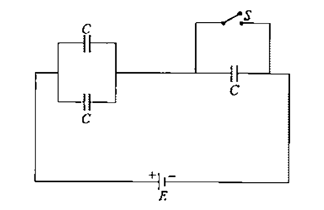
View SolutionIn the circuit shown, each capacitor has a capacitance C, The cell voltage is E, Find the amount of charge flowing through the switch when it is closed and also find the heat dissipated in the circuit when the switch is closed.
View Solution
Knowledge Check
In the circuit shown in figure, the capacitor is charged with a cell of 5V.If the switch is closed at t=0, then at t=12s, charge on the capacitor is
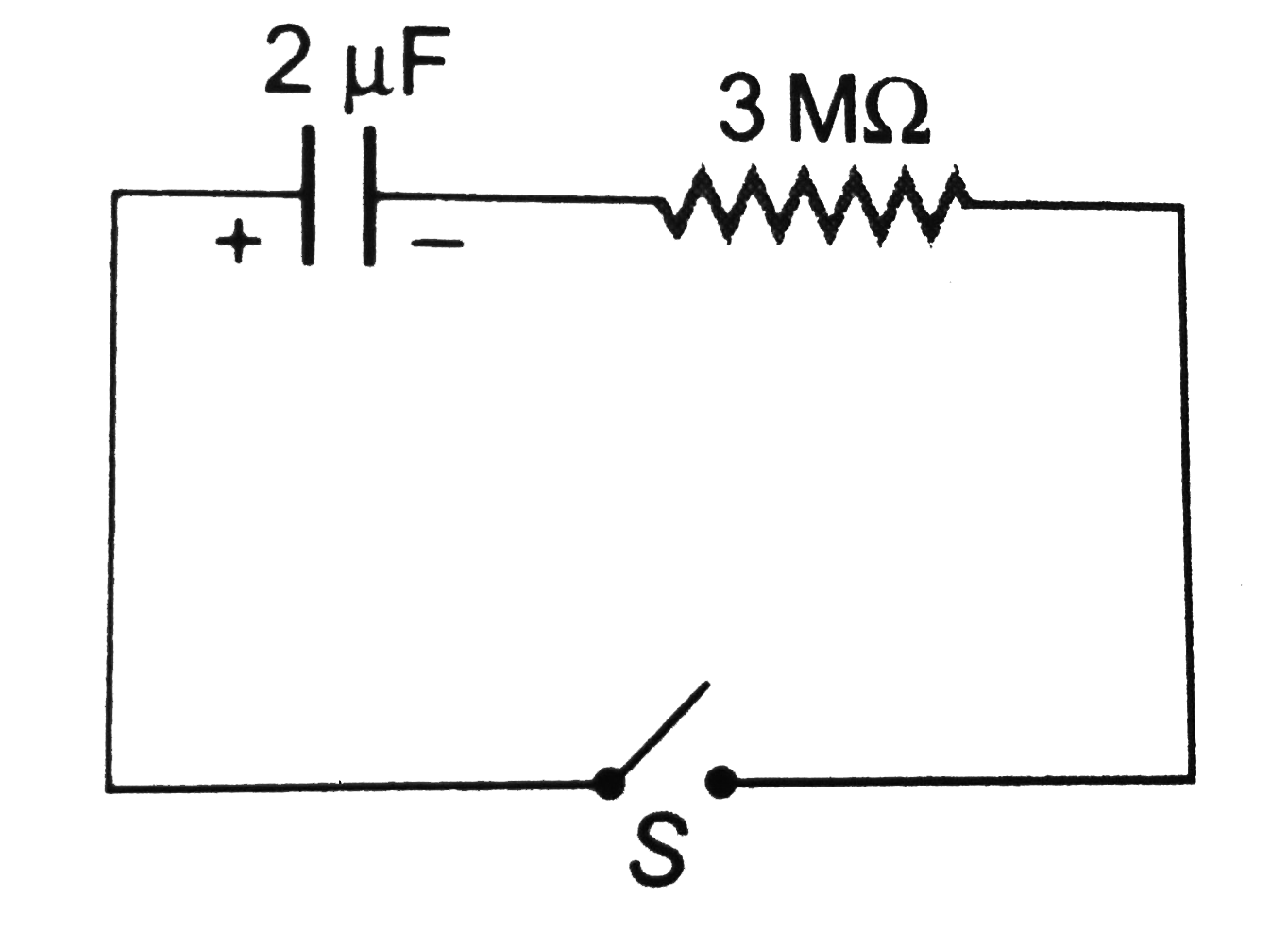 A(0.37)10μCB(0.37)210μCC(0.63)10μCD(0.63)210μC
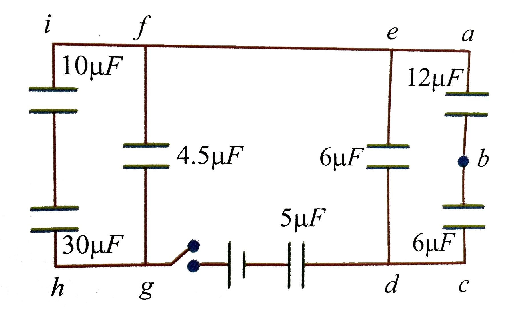
In the circuit diagram shown here seven capacitors are connected to a source of emf E. Initially, the switch S is closed and steady state attained. Now, the potential difference between the points 'a' and 'b' is 4 volt. Now, answer the following :
 .
.
The emf E of the battery is :A46 VB26 VC14 VD10 VIn the circuit shown, the capacitor C1 is initially charged with charge q0. The switch S is closed at time t = 0 . The charge on C2 after time t is
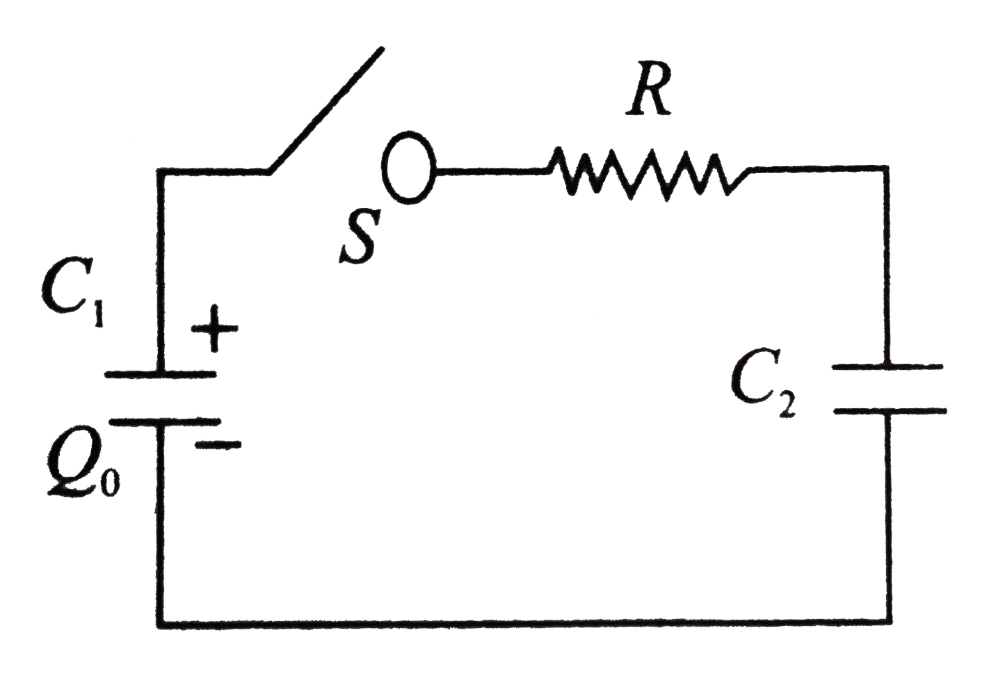 Aq0C1C1+C2(1−e−t(C1+C2)C1C2R)Bq0C2C1+C2(1−e−t(C1+C2)C1C2R)Cq0C1C1+C2(1−e−tC2R)Dq0C2C1+C2(1−e−tC2R)
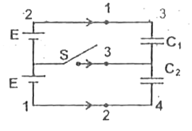
In the circuit shown, the emf of each battery is E. Find the charges that will flow when the switch S is closed, through sections 1, 2 and 3 in the directions indicated by the arrows.
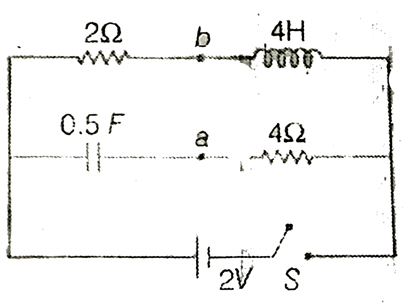
View SolutionIn the circuit shown. Initially the capacitor is uncharged. The switch S is closed at time t=0. Then
View Solution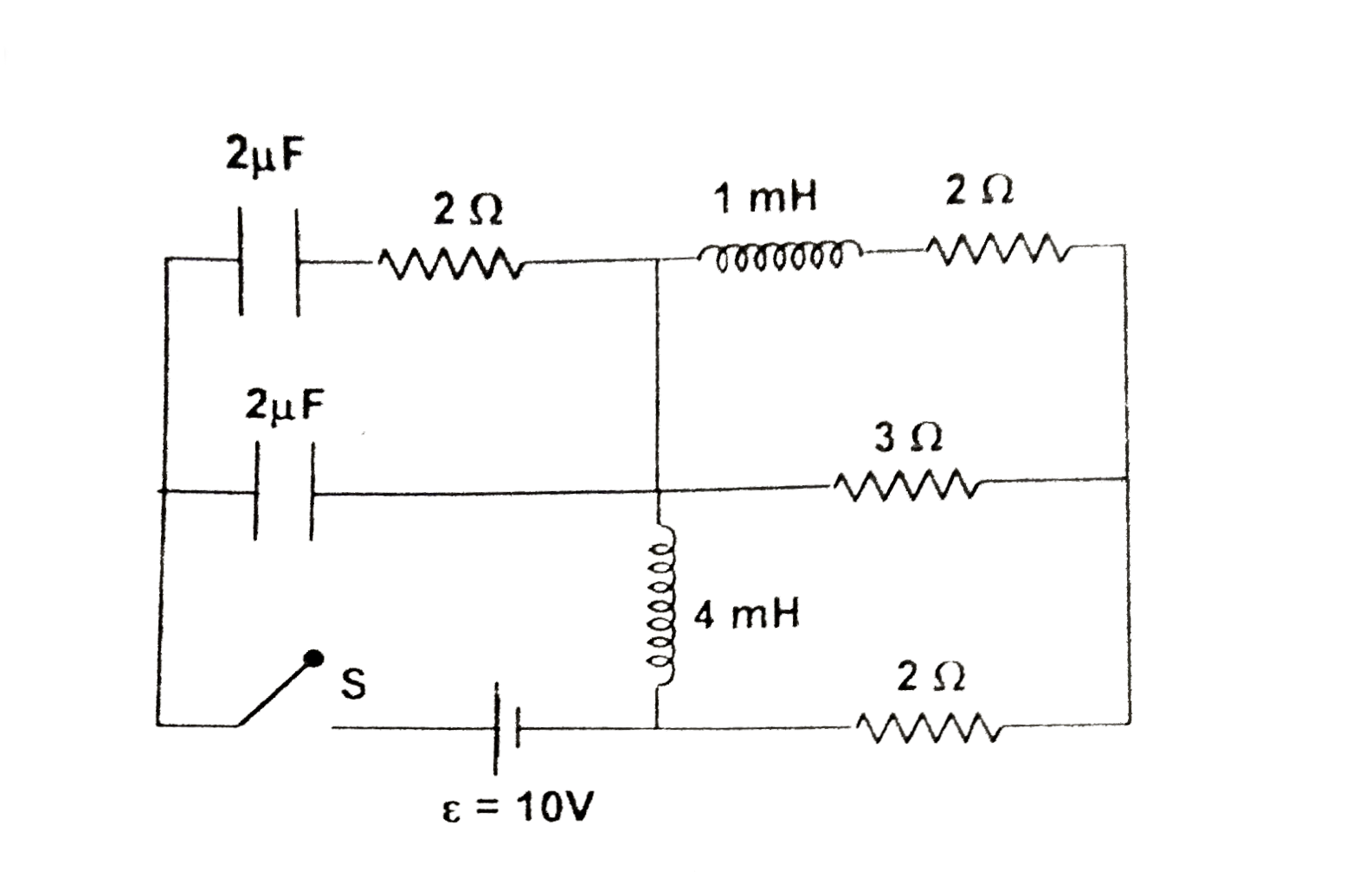
In the circuit shown, all the capacitors are initially uncharged. The current through the battery just after closing the switch 'S' is
View SolutionIn the circuit shown in the diagram, E is the e.m.f of the cell, connected to two resistances. Each of magnitude R and a capacitor of capacitance C as shown in the diagram. If the switch key K is closed at time t=0, the growth of potential V across the capacitor with be correctly given by
 .
.
View SolutionIn the circuit of figure, the battery emf is g the resitance is R and the capacitance is C. The switch S is closed for a long time interval, and zero potential difference is measured across the capacitor

After the switch is opened. the potential difference across the capacitor reaches a maximum value of ΔV. What is the value of the inductance?
View Solution
